


© UPLIFT Desk
• 1-800-349-3839 • 1-512-614-3152 • [email protected] • upliftdesk.com
6
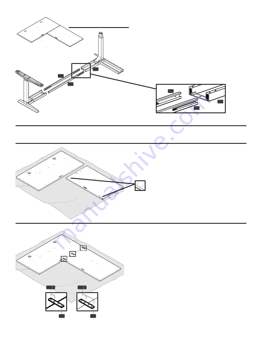
Step 6.2- Left-return.
When upside down on the ground, the Left-return
configuration will look like this.
Lay down one Upper crossbar (C6) and the Open
crossbar (C7) and slide the Right-leg assembly and
Corner-leg assembly onto them.
Note:
you need to
use the Open crossbar (C7) on the inside hole of the
Corner leg assembly’s Frame end (C4). The crossbars
should be aligned as shown with the slots further from
the floor (see diagram below). If they do not slide in
all the way, flip them over and reinsert them the cor
-
rect way.
The slots on all Crossbars are offset, and should be further from the floor.
C7
C7
C4
C4
Note: We will be focusing on the Left-return configuration for the rest of the assembly instructions.
Step 7
Lay down a blanket and place your Desktops on it to
protect them from scratches. The pre-drilled holes
should be facing UP. Slide the smaller Return desktop,
against the Main desktop.
Note:
The holes for the Keypad should be fac-
ing the inside.
Step 8
Make sure both Main and Return desktops are flush.
Line up the Support brackets (H8) over their corre-
sponding pre-drilled holes.
Note: Some desktops use only two (2) Support
brackets (H8) and others use three (3).
Screw two (2) #10x5/8’’ Wood screws (H3a) all the
way into the Support bracket on the side overlapping
the Main desktop (fig. 1).
On the Return desktop, carefully align and insert a
third Wood screw (H3a) through a hole, but only part-
way (fig. 2). At this point, this screw is only used to
keep the Return desktop from moving around. You
will remove this third screw in a later step.
(fig 1)
(fig 2)
H8
H8
H3 a
H3 a
C6
C6


