background image

UR10

56

User Manual

C

o

p

yr

ig

h

t

©

2

0

0

9

2

0

2

0

b

y

U

n

iv

e

rs

a

R

o

b

o

ts

 A

/S

.

A

ll

ri

g

h

ts

re

s

e

rv

e

d

.

Summary of Contents for UR10/CB3

Page 1: ...Universal Robots User Manual UR10 CB3 Original instructions en...

Page 2: ...hout notice and should not be construed as a commitment by Universal Robots A S This document is periodically reviewed and revised Universal Robots A S assumes no responsibility for any errors or omis...

Page 3: ...top 11 1 5 9 Movement With and Without Drive Power 12 1 6 Safety related Functions and Interfaces 13 1 6 1 Introduction 13 1 6 2 Stopping times of the Safety System 14 1 6 3 Limiting Safety related Fu...

Page 4: ...Functions Tables 77 1 18 1 Table 1 Safety Functions SF Descriptions 77 1 19 Table 2 Compliance and ISO 13849 1 Functional Safety Information 81 Part II PolyScope Manual 85 1 20 Safety Configuration 87...

Page 5: ...ice and Operational Mode 105 System Emergency Stop 106 Robot Moving 107 Robot Not Stopping 107 Reduced Mode 107 Not Reduced Mode 107 1 21 Begin programming 109 1 21 1 Introduction 109 1 21 2 Getting S...

Page 6: ...stallation Default Program 149 1 23 16 Log Tab 151 1 23 17 Load Screen 153 Path history 154 File selection area 154 File filter 154 File field 154 Open button 154 Cancel button 154 Action buttons 154...

Page 7: ...26 Force value selection 194 1 24 27 Limits selection 195 1 24 28 Test force settings 195 1 24 29 Command Pallet 196 1 24 30 Command Seek 197 1 24 31 Command Conveyor Tracking 201 1 24 32 Command Supp...

Page 8: ...P 67 program template 219 1 28 2 I O overview and troubleshooting 221 1 28 3 Program structure functionality 223 1 28 4 I O action and wait 230 1 29 Installing and uninstalling the interface 231 1 29...

Page 9: ...ns the Robot Arm the other contains Control Box with Teach Pendant Mounting bracket for the Control Box Mounting bracket for the Teach Pendant Key for opening the Control Box Cable for connecting the...

Page 10: ...rsions of this manual PolyScope Manual The Service Manual with instructions for troubleshooting maintenance and repair The Script Manual for advanced users 1 4 1 UR The UR site http www universal robo...

Page 11: ...Part I Hardware Installation Manual User Manual 3 UR10 Part I Hardware Installation Manual Copyright 2009 2020 by Universal Robots A S All rights reserved...

Page 12: ...UR10 4 User Manual Part I Hardware Installation Manual Copyright 2009 2020 by Universal Robots A S All rights reserved...

Page 13: ...e held responsible for any damages caused to the robot or any other equipment due to programming errors or malfunctioning of the robot 1 5 2 Validity and Responsibility The information in this manual...

Page 14: ...product WARNING This indicates an imminently hazardous electrical situation which if not avoided could result in death or serious injury WARNING This indicates an imminently hazardous situation which...

Page 15: ...anual Other warnings and cautions are present throughout this manual WARNING You must install the robot and all electrical equipment according to the specifications and warnings found in chapters 1 8...

Page 16: ...shall only be used in installations where the risk assessment allows it Tool end effectors and obstacles shall not have sharp edges or pinch points 10 Make sure to warn people to keep their heads and...

Page 17: ...ields can damage the robot 1 5 6 Intended Use UR robots are industrial robots intended to handle tools end effectors and fixtures or to process or transfer components or products For details about the...

Page 18: ...required for the specific robot application Identifying the correct safety configuration settings is a particularly important part of developing collaborative robot applications See chapter 1 6 Safet...

Page 19: ...robot wrist 1 and robot wrist 2 Joint 3 and Joint 4 4 Penetration of skin by sharp edges and sharp points on tool end effector or tool end effector connector 5 Penetration of skin by sharp edges and s...

Page 20: ...joint brake has a friction clutch which enables movement during high forced torque 2 Manual brake release Remove the joint cover by removing the few M3 screws that fix it Release the brake by pushing...

Page 21: ...e done according to the risk assessment that the integrator conducts for a specific robot application see section 1 5 7 Risk Assessment on page 10 in chapter 1 5 Safety on page 5 2 If the robot discov...

Page 22: ...ed horizontally Speed The TCP speed limit of the safety system is set to the described limit Payload maximum payload handled by the robot attached to the TCP 10 kg The worst case stopping time for Sto...

Page 23: ...zard by preventing the robot moving into this region of its workspace WARNING If the robot is used in manual hand guiding applications with linear movements the joint speed limit must be set to maximu...

Page 24: ...educed mode to Normal mode OR changing Normal mode to Reduced mode It allows the robot to adapt e g the speed to the new safety limits Recovery Mode When a safety limit is violated the safety system m...

Page 25: ...ed System Emergency Stop Configurable Input Performs a Stop Category 1 To avoid deadlocks this signal will not be forwarded to other machines through the System emergency stop output Safeguard Stop De...

Page 26: ...is at rest the powering off is finalized within 600 ms Furthermore after a Safeguard Stop input the robot arm is only allowed to start moving again after a positive edge on the safeguard reset input...

Page 27: ...Logic high when the robot is stopped or in the process of stopping due to an emergency stop or safeguard stop Otherwise it will be logic low Reduced Mode Logic low when the safety system is in Reduced...

Page 28: ...UR10 20 User Manual Copyright 2009 2020 by Universal Robots A S All rights reserved...

Page 29: ...of the robot The controller box shall be lifted by the handle WARNING 1 Make sure not to overload your back or other bodyparts when the equipment is lifted Use proper lifting equipment All regional a...

Page 30: ...UR10 22 User Manual Copyright 2009 2020 by Universal Robots A S All rights reserved...

Page 31: ...mounting place for the robot is chosen Moving the tool close to the cylindrical volume should be avoided if possible because it causes the joints to move fast even though the tool is moving slowly cau...

Page 32: ...shall be vibration free If the robot is mounted on a linear axis or a moving platform then the acceleration of the moving mounting base shall be very low A high acceleration might cause the robot to...

Page 33: ...urate repositioning of the tool is desired the 6 hole is provided for use with a pin Figure 6 2 shows where to drill holes and mount the screws WARNING 1 Make sure the tool is properly and securely bo...

Page 34: ...no one can trip over the cable WARNING 1 Make sure that the control box teach pendant and cables do not come into contact with liquids A wet control box could cause death 2 The control box and teach p...

Page 35: ...0 600 800 2 4 6 8 10 Center of gravity offset mm 6 3 Relationship between the maximum allowed payload and the center of gravity offset User Manual 27 UR10 Copyright 2009 2020 by Universal Robots A S A...

Page 36: ...UR10 28 User Manual Copyright 2009 2020 by Universal Robots A S All rights reserved...

Page 37: ...autions The following warnings and cautions must be observed when a robot application is designed and installed The warnings and cautions also apply for service work WARNING 1 Never connect safety sig...

Page 38: ...at all shavings are removed before reinstalling the plate Remember to use correct gland sizes CAUTION 1 The robot has been tested according to international IEC standards for EMC ElectroMagnetic Compa...

Page 39: ...e more in part Part II PolyScope Manual on page 85 How to use the digital I O is described in the following subsections The section describing the common specifications must be observed Common specifi...

Page 40: ...utputs COx DOx Current 0 1 A COx DOx Voltage drop 0 0 5 V COx DOx Leakage current 0 0 1 mA COx DOx Function PNP Type COx DOx IEC 61131 2 1A Type Digital Inputs EIx SIx CIx DIx Voltage 3 30 V EIx SIx C...

Page 41: ...ergency stop equipment only The Safeguard Stop input is for all kinds of safety related protective equipment The functional difference is shown below Emergency Stop Safeguard Stop Robot stops moving Y...

Page 42: ...ety function could be overridden Default safety configuration The robot is shipped with a default configuration which enables operation without any additional safety equipment see illustration below 2...

Page 43: ...V CI0 Configurable Inputs 24V CI5 24V CI6 24V CI7 24V CI4 0V CO1 0V CO2 0V CO3 0V CO0 Configurable Outputs 0V CO5 0V CO6 0V CO7 0V CO4 A B If more than two UR robots or other machines need to be conne...

Page 44: ...meter is required The reset button must be a two channel type In this example the I O configured for reset is CI0 CI1 see below 24V EI1 24V SI0 24V SI1 24V EI0 Safety Safeguard7Stop Emergency7Stop 24V...

Page 45: ...eral purpose I O can be used to drive equipment like pneumatic relays directly or for communication with other PLC systems All digital outputs can be disabled automatically when program execution is s...

Page 46: ...g I O interface is the green terminal It can be used to set or measure voltage 0 10V or current 4 20mA from and to other equipment The following is recommended to achieve the highest accuracy Use the...

Page 47: ...Voltage 0 10 V AOx AG Current 20 20 mA AOx AG Resistance 1 ohm AOx AG Resolution 12 bit The following examples show how to use the analog I O Using an analog output Below is an example of how to cont...

Page 48: ...intended for short time activation only The on input works in the same way as the power button Always use the off input for remote off control as this signal allows the control box to save open files...

Page 49: ...robot there is a small connector with eight pins see illustration below This connector provides power and control signals for grippers and sensors used on a specific robot tool The following industri...

Page 50: ...the tool WARNING 1 Connect tools and grippers such that an interruption of power does not create any hazards e g a work piece falling out of the tool 2 Take care when using 12V since an error made by...

Page 51: ...ind that there is voltage between the POWER connection and the shield ground even when the load is turned off TO0 POWER Note It is highly recommended to use a protective diode for inductive loads as s...

Page 52: ...ution 12 bit Two examples of how to use analog inputs are shown in the following subsections CAUTION 1 Analog inputs are not protected against over voltage in current mode Overrating the limit in the...

Page 53: ...ee more in part Part II PolyScope Manual on page 85 Remote access and control The electrical specifications are shown below Parameter Min Typ Max Unit Communication speed 10 1000 Mb s 1 9 6 Mains conn...

Page 54: ...rectly Electrical connection to earth Use the unused bolts associated with grounding symbols inside the controller box to create common grounding of all equipment in the system The grounding conductor...

Page 55: ...the connector is properly locked before turning on the robot arm Disconnecting the robot cable may only be done when the robot power is turned off CAUTION 1 Do not disconnect the robot cable when the...

Page 56: ...UR10 48 User Manual Copyright 2009 2020 by Universal Robots A S All rights reserved...

Page 57: ...ns shall also be tested The purpose of maintenance and repair work is to ensure that the system is kept operational or in the event of a fault to return the system to an operational state Repair work...

Page 58: ...g the robot arm or control box 1 10 2 Cleaning Everyday cleaning You can wipe away any dust dirt oil observed on the robot arm using a cloth and one of the following cleaning agents Water Isopropyl al...

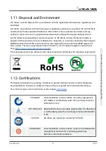
Page 59: ...here https www ewrn org national registers The following symbols are affixed on the robot to indicate conformity with the above legislations 1 12 Certifications Third party certification is voluntary...

Page 60: ...ontinuous internal testing and end of line test procedures UR testing processes undergo continuous review and improvement Declarations According to EU directives Although they are primarily relevant f...

Page 61: ...directives above Information on both electric and electronic equipment waste is in chapter 7 Information on standards applied during the development of the robot is in appendix C 2004 108 EC Electroma...

Page 62: ...UR10 54 User Manual Copyright 2009 2020 by Universal Robots A S All rights reserved...

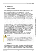
Page 63: ...s Statutory Rights nor the manufacturer s liability for death or personal injury resulting from its negligence The duration of the Warranty shall not be extended by services rendered under the terms o...

Page 64: ...UR10 56 User Manual Copyright 2009 2020 by Universal Robots A S All rights reserved...

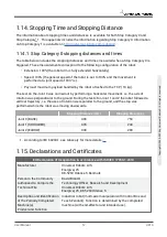
Page 65: ...perpendicular to the ground During the tests for Joint 1 and 2 the robot followed a vertical trajectory i e the axes of rotation were parallel to the ground and the stop was performed while the robot...

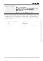
Page 66: ...ccordance with Part B of Annex VII of the Machinery Directive II Low voltage Directive 2014 35 EU Reference the LVD and the harmonized standards used below III EMC Directive 2014 30 EU Reference the E...

Page 67: ...2 27 2008 III IEC 60068 2 1 2007 III IEC 60068 2 2 2007 III IEC 61326 3 1 2008 The manufacturer or his authorized representative shall transmit relevant information about the partly completed machine...

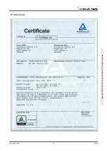
Page 68: ...Safety System Certificate UR10 60 User Manual Copyright 2009 2020 by Universal Robots A S All rights reserved...

Page 69: ...TUV Rheinland User Manual 61 UR10 Copyright 2009 2020 by Universal Robots A S All rights reserved...

Page 70: ...1 The certificate is limited to the particulate cleanliness The product was tested according to VDI 2083 Part 9 1 in August 2016 The implementation of the testing and certification is carried out by...

Page 71: ...ate is limited to the particulate cleanliness The product was tested according to VDI 2083 Part 9 1 in August 2016 The implementation of the testing and certification is carried out by T V S D Industr...

Page 72: ...China RoHS UR10 64 User Manual Copyright 2009 2020 by Universal Robots A S All rights reserved...

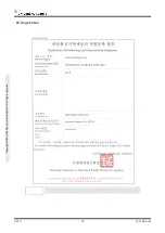
Page 73: ...KCC Safety User Manual 65 UR10 Copyright 2009 2020 by Universal Robots A S All rights reserved...

Page 74: ...KC Registration UR10 66 User Manual Copyright 2009 2020 by Universal Robots A S All rights reserved...

Page 75: ...8 Other document s Conclusion The three robot arms UR3 UR5 and UR10 including their control boxes and Teach Pendants have been tested according to the below listed standards The test results are given...

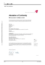
Page 76: ...onal Telecom Administration part of the Energy Agency in Denmark to carry out tasks referred to in Annex III of the European Council EMC Directive The attestation of conformity is in accordance with t...

Page 77: ...rds is only guaranteed if all assembly instructions safety instructions and guidance in this manual are followed ISO 13849 1 2006 PLd ISO 13849 1 2015 PLd ISO 13849 2 2012 EN ISO 13849 1 2008 E PLd 20...

Page 78: ...traditional robots UR robots are designed to work without a fence using built in power and force limiting collaborative safety functions and therefore without a hazardous safeguarded space defined by...

Page 79: ...robot manufacturer and robot integrator UR robots comply with the parts that are relevant for the raw robots themselves and the integrator can choose to use the TS when integrating the robots This TS...

Page 80: ...o not disturb other equipment IEC 61326 3 1 2008 EN 61326 3 1 2008 Electrical equipment for measurement control and laboratory use EMC requirements Part 3 1 Immunity requirements for safety related sy...

Page 81: ...29 A2 2013 Degrees of protection provided by enclosures IP Code This standard defines enclosure ratings regarding protection against dust and water UR robots are designed and classified with an IP cod...

Page 82: ...ed in the Part I Hardware Installation Manual on page 3 IEC 60068 2 1 2007 IEC 60068 2 2 2007 IEC 60068 2 27 2008 IEC 60068 2 64 2008 EN 60068 2 1 2007 EN 60068 2 2 2007 EN 60068 2 27 2009 EN 60068 2...

Page 83: ...rinciples requirements and tests Part 5 Comprehensive method for determining clearances and creepage distances equal to or less than 2 mm The electrical circuitry of UR robots is designed in complianc...

Page 84: ...cation TCP IP 1000 Mbit IEEE 802 3u 100BASE T Ethernet socket modbus TCP EtherNet IP Adapter Profinet Programming PolyScope graphical user interface on 12 touchscreen Noise 72 dB A IP classification I...

Page 85: ...itiated by each microprocessor SF1 Command1 all joints to stop and upon all joints coming to a standstill state power is removed This is a Cat 1 stop per IEC 60204 1 The stopping times of the SF0 and...

Page 86: ...nt can have its own limit Directly limits the set of allowed joint speeds which the joints are allowed to perform It is set directly in the safety setup part of the User Interface where you can enter...

Page 87: ...t they are tolerated For the integrated functional safety rating with an external Estop device add the PFHd of the UR Estop function SF0 or SF1 to the PFHd of the external logic if any and its compone...

Page 88: ...RD Certified SF Safety Function Description What is controlled Robot Reduced Mode Internal Logic and Outputs with Dual Inputs 1 through 4 Reduced Mode can be initiated by a safety plane boundary start...

Page 89: ...effect When High the mode is programming or teach Must be used with an Enabling Device as a safety input When in Teach Program Mode switch inputs high enabling device is required for operation When in...

Page 90: ...Joint Torque Limit internal factory setting factory setting Cat 0 NA 2 3 15E 07 SF6 TCP Pose Limit Limits Cat 0 NA 2 3 15E 07 SF7 TCP Speed Limit Limits Cat 0 NA 2 3 15E 07 TUV NORD Certified SF Safet...

Page 91: ...tion Cat 0 immediate stop NA 2 3 15E 07 TUV NORD Certified SF Safety Function Limits or USER configuration or Factory Setting Stop Category per IEC 60204 1 IEC 61800 5 2 Stop power to final switching...

Page 92: ...UR10 84 User Manual Copyright 2009 2020 by Universal Robots A S All rights reserved...

Page 93: ...Part II PolyScope Manual User Manual 85 UR10 Part II PolyScope Manual Copyright 2009 2020 by Universal Robots A S All rights reserved...

Page 94: ...UR10 86 User Manual Part II PolyScope Manual Copyright 2009 2020 by Universal Robots A S All rights reserved...

Page 95: ...applied according to the risk assessment conducted by the integrator and before the robot arm is powered on for the first time 3 All safety configuration settings accessible on this screen and its su...

Page 96: ...ity of individual joints and serve to further limit the speed of the robot arm The joint position limits define the allowed position range of individual joints in joint space For further details see 1...

Page 97: ...defined below Configuration Synchronized Shows the GUI installation is identical to the currently applied safety configuration No changes have been made Configuration Altered Shows the GUI installati...

Page 98: ...tolerances prevent safety violations while allowing for fluctuations in program behavior For example when handling a heavy payload there may be situations where the Robot Arm needs to briefly operate...

Page 99: ...uired to be more restrictive than their Normal mode counterparts When a safety limit from the active limit set is violated the robot arm performs a Stop Category 0 If an active safety limit such as a...

Page 100: ...ld at the bottom of the screen and the Unlock button is pressed The screen can be locked again by clicking the Lock button The Safety tab is automatically locked when navigating away from the safety c...

Page 101: ...limit for the maximum force that the robot TCP exerts on the environment Power A limit for the maximum mechanical work produced by the robot on the environment considering that the payload is part of...

Page 102: ...en the current speed is within approximately 250 mm s of the limit Basic Settings The initial general limits subpanel shown as the default screen features a slider with four predefined sets of values...

Page 103: ...sted at the end of the row that corresponds to it When a program is running the speed of the robot arm is automatically adjusted in order to not exceed any of the entered values minus the tolerance se...

Page 104: ...of the position limit The Wrist 3 position range is unlimited by default When using cables attached to the robot you must first disable the Unrestricted Range for Wrist 3 checkbox to avoid cable tens...

Page 105: ...e range resulting from adding the first tolerance to the entered minimum value and subtracting the second tolerance from the entered maximum value if it continues moving along the predicted trajectory...

Page 106: ...through them Selecting a boundary to configure The Safety Boundaries panel on the left side of the tab is used to select a boundary limit to configure To set up a safety plane click on one of the top...

Page 107: ...ing the current orientation of the robot tool The inside of the cone represents the allowed area for the tool orientation vector When a plane or the tool orientation boundary limit is configured but n...

Page 108: ...ated by a positioned over the feature selector Click the button next to the selector to update the limit with the current position and orientation of the feature The icon is also displayed if the sele...

Page 109: ...rm are limited by the respective limit set By default the safety system is in Normal mode It transitions into Reduced mode whenever one of the following situations occurs 1 The robot TCP is positioned...

Page 110: ...ture deceleration can occur only when transitioning from Normal to Reduced mode Tool Boundary configuration The Tool Boundary Properties panel at the bottom of the tab defines a limit on the orientati...

Page 111: ...ature selector Click the Safety mode The drop down menu on the right hand side of the Tool Boundary Properties panel is used to choose the safety mode for the tool orientation boundary The available o...

Page 112: ...tput signals Note Applying a safety function to a set of pins will override any I O actions specified for pins in the I O Setup see 1 23 8 Installation I O Setup on page 132 Input Signals For input si...

Page 113: ...feguard Stop inputs SI0 and SI1 see the Hardware Installation Manual fully determine whether the Safeguard Stopped state is active or not Three Position Enabling Device and Operational Mode These allo...

Page 114: ...onfirmed the Welcome screen is automatically shown The Welcome screen is also automatically displayed when the operational mode changes from Programming to Running The physical mode selector if used m...

Page 115: ...inery must require manual action in order to resume Robot Moving A low signal is given whenever the robot arm is in a mobile state When the robot arm is in a fixed position a high signal is given Robo...

Page 116: ...UR10 108 User Manual Copyright 2009 2020 by Universal Robots A S All rights reserved...

Page 117: ...ones The following section gets you started with the robot Afterwards the screens and functionality of PolyScope are explained in more detail WARNING 1 The Hardware Installation Manual contains import...

Page 118: ...ar on the touch screen After about one minute a few buttons appear on the screen and a popup guides the user to the initialization screen see 1 21 6 Initialization Screen on page 114 To shut down the...

Page 119: ...t allows a Robot arm that has been started up to move between two waypoints 1 Touch the Program Robot button and select Empty Program 2 Touch the Next button bottom right so that the empty line is sel...

Page 120: ...default values Always conduct a risk assessment before placing the robot into operation 1 21 4 PolyScope Programming Interface PolyScope runs on the touch sensitive screen attached to the control box...

Page 121: ...ouching them launches an on screen keypad or keyboard The various screens of PolyScope are described in the following sections 1 21 5 Welcome Screen After booting up the controller PC the welcome scre...

Page 122: ...red on and ready for normal operation The text appearing next to the LED further specifies the current state of the robot arm Active payload and installation When the robot arm is powered on the paylo...

Page 123: ...he robot arm After the controller PC boots up the button needs to be tapped once to power the robot arm on The robot arm state then turns to Power on and subsequently to Idle Note that when an emergen...

Page 124: ...UR10 116 User Manual Copyright 2009 2020 by Universal Robots A S All rights reserved...

Page 125: ...the names of the input and output ports can be found in the Input and Output selectors Some special functions are found in Function The expression is checked for grammatical errors when the Ok button...

Page 126: ...anes are visualized in yellow and black with a small arrow representing the plane normal which indicates the side of the plane on which the robot TCP is allowed to be positioned Trigger planes are dis...

Page 127: ...degrees Values can be edited by clicking on the coordinate Clicking on the or buttons just to the right of a box allows you to add or subtract an amount to from the current value Pressing and holding...

Page 128: ...Cancel button Clicking the Cancel button leaves the screen discarding all changes UR10 120 User Manual Copyright 2009 2020 by Universal Robots A S All rights reserved...

Page 129: ...to a safety or trigger plane or the orientation of robot tool is near the tool orientation boundary limit see 1 20 12 Boundaries on page 97 a 3D representation of the proximate boundary limit is shown...

Page 130: ...ding down a translate arrow top will move the tool tip of the robot in the direction indicated Holding down a rotate arrow bottom will change the orientation of the robot tool in the indicated directi...

Page 131: ...utside the reach of the robot arm 1 23 2 I O Tab On this screen you can always monitor and set the live I O signals from to the robot control box The screen displays the current state of the I O inclu...

Page 132: ...controller when a program is saved Selecting a URCap in Tool Output removes access to the Domain Settings for the analog Tool Inputs 1 23 3 MODBUS The screenshot below displays the MODBUS client I O...

Page 133: ...out to perform CAUTION Compare the animation with the position of the real robot arm and make sure that the robot arm can safely perform the movement without hitting any obstacles CAUTION The automove...

Page 134: ...t in the I O tab see 1 23 2 I O Tab on page 123 It is possible to have more than one installation file for the robot Programs created will use the active installation and will load this installation a...

Page 135: ...ot moves the TCP to the position and orientation saved within the waypoint When programmed for linear motion the TCP moves linearly Position The X Y Z coordinates specify the TCP position When all val...

Page 136: ...CP When moving linearly the robot always uses the active TCP to determine the TCP offset The active TCP can be changed using a Move command see 1 24 4 Command Move on page 161 or a Set command Default...

Page 137: ...CP a fourth position can be used to further verify the calculation is correct The quality of each saved point with respect to the calculated TCP is indicated using a green yellow or red LED on the cor...

Page 138: ...CZ The settings apply to all defined TCPs Installations created before version 3 8 support the center of gravity being set to the TCP if they were previously set If the center of gravity is manually...

Page 139: ...lat table or floor no change is needed on this screen However if the Robot arm is ceiling mounted wall mounted or mounted at an angle this needs to be adjusted using the buttons The buttons on the rig...

Page 140: ...teger and float The general purpose registers can be accessed by a fieldbus e g Profinet and EtherNet IP I O Signal Type To limit the number of signals listed in the Input and Output sections use the...

Page 141: ...sing edge Freedrive When the input is high the robot is in freedrive similar to the freedrive button The input is ignored if a program is running or other conditions disallow freedrive WARNING If the...

Page 142: ...stallation Safety See chapter 1 20 Safety Configuration on page 87 1 23 10 Installation Variables Variables created on the Installation Variables screen are called installation variables and are used...

Page 143: ...used in this installation 4 Select the variable in the list then tap Edit Value to change the value of the installation variable 5 Once the variable is configured you must save the installation itself...

Page 144: ...programs Refresh Push this button to refresh all MODBUS connections Refreshing disconnects all modbus units and connects them back again All statistics are cleared Add unit Push this button to add a...

Page 145: ...tity which is read from the MODBUS unit on the coil specified in the address field of the signal Function code 0x02 Read Discrete Inputs is used Digital output A digital output coil is a one bit quant...

Page 146: ...isplayed The MODBUS TCP Exception responses are E1 ILLEGAL FUNCTION 0x01 The function code received in the query is not an allowable action for the server or slave E2 ILLEGAL DATA ADDRESS 0x02 The fun...

Page 147: ...recommended to consult the manual of the remote MODBUS device to verify its functionality when changing slave address Reconnect count Number of times TCP connection was closed and connected again Conn...

Page 148: ...obot arm These objects can be tables other machines workpieces vision systems blanks or boundaries existing around the robot arm The robot includes two predefined features listed below with poses defi...

Page 149: ...ere possible as they are based on more input points More input points mean higher precision For example you can accurately define the direction of a linear conveyor by defining two points of a Line fe...

Page 150: ...7 When a feature is chosen as a reference the Move Tool buttons for translation and rotation operate in the selected feature space see Feature and Tool Position on page 122 and Move Tool on page 122 r...

Page 151: ...n of the Robot arm The point feature pose is defined as the position and orientation of the TCP Adding a Point 1 In Installation select Features 2 Under Features select Point Line feature The line fea...

Page 152: ...nate system The z axis is defined by the projection of the z axis of p1 onto the plane perpendicular to the line The position of the line coordinate system is the same as the position of p1 Plane Feat...

Page 153: ...oduct of the x axis and the y axis as illustrated below NOTE You can re teach the plane in the opposite direction of the x axis if you want that plane to be normal in the opposite direction Modify an...

Page 154: ...mmand configured relative to the plane can be easily applied on additional robots by just updating the installation with the actual position of the table The concept applies to a number of Features in...

Page 155: ...0 0 0 P1_var pose_trans P1_var o MoveL Feature P1_var wp1 wp2 wp3 wp4 15 6 Applying an offset to the plane feature Robot Program MoveJ S1 if digital_input 0 then P1_var P1 else P1_var P2 MoveL Featur...

Page 156: ...as well as linear or circular conveyors Conveyor Parameters Incremental encoders can be connected to Digital Inputs 0 to 3 Decoding of digital signals runs at 40kHz Using a Quadrature encoder requiri...

Page 157: ...2 Select the Rotate tool with conveyor checkbox for the tool orientation to track the conveyor rotation 1 23 14 Smooth Transition Between Safety Modes When switching between safety modes during event...

Page 158: ...not be required in this case 2 Use caution when the signal level is set to LOW Input signals are low by default leading the program to automatically run without being triggered by an external signal L...

Page 159: ...ut signal edge transition the Robot arm is completely initialized regardless of the visible screen Brake Release is the final initialization stage During Brake Release the Robot arm makes a minor move...

Page 160: ...ll be filtered Some log messages are designed to provide more information that is accessible by selecting the log entry Saving Error Reports When an error occurs in PolyScope a log of the error is gen...

Page 161: ...ference lies in which actions are available to the user In the basic load screen the user will only be able to access files not modify or delete them Furthermore the user is not allowed to leave the d...

Page 162: ...old9 is the oldest File field Here the currently selected file is shown The user has the option to manually enter the file name of a file by clicking on the keyboard icon to the right of the field Thi...

Page 163: ...l that can run exclusively pre written programs Furthermore in this tab a default program can be automatically loaded and started based on an external input signal edge transition see 1 23 15 Installa...

Page 164: ...UR10 156 User Manual Copyright 2009 2020 by Universal Robots A S All rights reserved...

Page 165: ...tart from either a template or from an existing saved robot program A template can provide the overall program structure so only the details of the program need to be filled in User Manual 157 UR10 Co...

Page 166: ...cking the command list or by using the Previous and Next buttons on the bottom right of the screen Commands can be inserted or removed using the Structure tab The program name is shown directly above...

Page 167: ...e program execution indicator icon marks the last command that was in the process of being executed Clicking the button with the icon below the Program Tree jumps to the current executing or the last...

Page 168: ...tay outside the robot workspace when the Play button is pressed The movement you programmed may be different than expected 2 Only use the Step button when it is absolutely necessary Make sure to stay...

Page 169: ...ber in the range from 2147483648 to 2147483647 32 bit float A floating point number decimal 32 bit string A sequence of characters pose A vector describing the location and orientation in Cartesian sp...

Page 170: ...s2 respectively and also a feature moveP moves the tool linearly with constant speed with circular blends and is intended for some process operations like gluing or dispensing The size of the blend r...

Page 171: ...ll adjusted be with respect to this If Use Tool Flange is selected no TCP is used and the motion under this Move command will be with respect to the tool flange i e no adjustments to the motion If the...

Page 172: ...n the feature selection menu If a feature variable named with the name of the feature suffixed by _var is selected robot arm movements except to Relative waypoints are relative to the actual value of...

Page 173: ...eds to be a valid feature selected at that Move command in order for this button to be pressable Waypoint names Waypoints automatically get a unique name The name can be changed by the user By selecti...

Page 174: ...exactly as long as the transition from the first trajectory to the second happens near this position The stop at WP_2 can be avoided by configuring a blend for the waypoint allowing the robot to calcu...

Page 175: ...4 Blend radius overlap not allowed Conditional blend trajectories The blend trajectory is affected both by the waypoint where the blend radius is set and the following one in the program tree That is...

Page 176: ...o potential final waypoints WP_F_1 and WP_ F_2 depending on a conditional expression The conditional if expression is evaluated when the robot arm enters the second blend Trajectory type combinations...

Page 177: ...ajectories that keep within the boundaries of the original trajectory in Cartesian space An example of a blend between different trajectory types bullet 2 can be seen in figure 16 7 WP_1 WP_2 WP_3 16...

Page 178: ...Caution if the velocities are very different e g by specifying advanced settings either velocity or time for a specific waypoint this can result in large deviations from the original trajectory as sho...

Page 179: ...ions left to right Note repeated relative positions can move the robot arm out of its workspace The distance here is the Cartesian distance between the TCP in the two positions The angle states how mu...

Page 180: ...r if the blend radius is set on a variable waypoint then the blend radius will not be checked for overlap see Blend parameters on page 166 If when running the program the blend radius overlaps a point...

Page 181: ...cal expression The Direction Vectors defines a custom code expression that is resolved to a unit vector For example for a vector of 2 1 0 the robot moves two units in the x direction for every unit in...

Page 182: ...rection move when the robot has moved a certain distance The velocity is ramped down so the robot stops exactly at the distance Expression This node can be used to stop the motion due to a custom prog...

Page 183: ...10 Command Wait Wait pauses I O signal or expression for a given amount of time If No Wait is selected nothing is done User Manual 175 UR10 Copyright 2009 2020 by Universal Robots A S All rights rese...

Page 184: ...used as the center of gravity the checkbox must be unchecked The active TCP can also be modified using a Set command by selecting the check box and choosing one of the TCP offsets from the menu If the...

Page 185: ...ng the on screen keyboard Messages are limited to a maximum of 255 characters The robot waits for the user operator to press the OK button under the popup before continuing the program If the Halt pro...

Page 186: ...1 24 13 Command Halt The program execution stops at this point UR10 178 User Manual Copyright 2009 2020 by Universal Robots A S All rights reserved...

Page 187: ...ent Gives the programmer an option to add a line of text to the program This line of text does not do anything during program execution User Manual 179 UR10 Copyright 2009 2020 by Universal Robots A S...

Page 188: ...label specific parts of a program to clean up the program tree and to make the program easier to read and navigate Folders have no impact on the program and its execution UR10 180 User Manual Copyrigh...

Page 189: ...created which can be used in expressions within the loop The loop variable counts from 0 to N 1 When looping using an expression as end condition PolyScope provides an option for continuously evaluati...

Page 190: ...tements to be evaluated while the contained lines are executed If an expression inside an If statement is evaluated as False the ElseIf or Else statements are followed NOTE If there are waypoints insi...

Page 191: ...ram parts that are needed several places A SubProgram can be a separate file on the disk and can also be hidden to protect against accidental changes to the SubProgram User Manual 183 UR10 Copyright 2...

Page 192: ...Call Subroutine A call to a Subroutine will run the program lines in the SubProgram and then return to the following line UR10 184 User Manual Copyright 2009 2020 by Universal Robots A S All rights r...

Page 193: ...to the variables An assignment puts the computed value of the right hand side into the variable on the left hand side This can be useful in complex programs User Manual 185 UR10 Copyright 2009 2020 by...

Page 194: ...ion Editor on page 117 File allows you to write edit or load URscript files You can find instructions for writing URscript in the Script Manual on the support website http www universal robots com sup...

Page 195: ...an output signal goes high the event program can wait for 200ms and then set it back to low again This can make the main program code a lot simpler in the case on an external machine triggering on a r...

Page 196: ...obot program A thread can be used to control an external machine independently of the robot arm A thread can communicate with the robot program with variables and output signals UR10 188 User Manual C...

Page 197: ...luated to match one of the cases the lines inside the Case are executed If a Default Case has been specified then the lines will be executed only if no other matching cases were found Each Switch can...

Page 198: ...s for specific parts of the program to run A program variable contains the time passed since a Timer started and can be seen in the Variables Tab and in the Run Tab UR10 190 User Manual Copyright 2009...

Page 199: ...r corner points where as for Box this is four of the eight corner points The programmer enters the number of positions along each of the edges of the pattern The robot controller then calculates the i...

Page 200: ...e name of the variable can be seen on the Pattern command screen The variable cycles through the numbers from 0 to X Y Z 1 the number of points in the pattern This variable can be manipulated using as...

Page 201: ...usly option is selected you can add an end_force_ mode script at the end of the expression to exit force control WARNING 1 Avoid high deceleration just before entering force mode 2 Avoid high accelera...

Page 202: ...will be perpendicular to the robot arm s motion and in the x y plane of the selected feature This can be useful when de burring along a complex path where a force is needed perpendicular to the TCP mo...

Page 203: ...he Freedrive button on the back of the Teach Pendant is pressed the robot will perform as if the program had reached this force command and this way the settings can be verified before actually runnin...

Page 204: ...3 Use the selector on the sequence command screen to define which of the waypoints in the sequence should correspond to the pattern positions Pallet Sequence Anchorable Sequence In a Pallet Sequence...

Page 205: ...r This function is made for working on stacks of items with varying item thickness or where the exact positions of the items are not known or too hard to program Stacking Destacking When programming a...

Page 206: ...the position and performs the special sequence The next time round the robot starts the search from the remembered position incremented by the item thickness along the direction The stacking is finish...

Page 207: ...t remembers the position and performs the special sequence The next time round the robot starts the search from the remembered position incremented by the item thickness along the direction Starting p...

Page 208: ...ously evaluating whether the next stack position has been reached When the expression is evaluated to True the special sequence is executed BeforeStart The optional BeforeStart sequence is run just be...

Page 209: ...e 148 provides options for configuring the robot to work with absolute and incremental encoders as well as linear and circular conveyors NOTE The Control Box can only accomodate one incremental encode...

Page 210: ...rical cone together with a vector indicating the current orientation of the robot tool The inside of the cone represents the allowed area for the tool orientation vector When the target robot TCP no l...

Page 211: ...etails for the new command go to the Command tab Commands can be moved cloned deleted using the buttons in the edit frame If a command has sub commands a triangle next to the command all sub commands...

Page 212: ...program runs It only appears when it has information to display The variables are ordered alphabetically by their names The variable names on this screen are shown with at most 50 characters and the...

Page 213: ...f the Keep value from previous run check box is selected the variable will be initialized to the value found on the Variables tab see 1 24 35 Variables Tab on the previous page This permits variables...

Page 214: ...UR10 206 User Manual Copyright 2009 2020 by Universal Robots A S All rights reserved...

Page 215: ...ord see 1 25 3 Set Password on page 210 Calibrate Screen Calibrates the touch of the touch screen see 1 25 4 Calibrate Screen on page 211 Setup Network Opens the interface for setting up the Ethernet...

Page 216: ...us screens of PolyScope as well as in the embedded help Tick off English programming to have the names of commands within robot programs written in English PolyScope needs to be restarted for changes...

Page 217: ...een instructions WARNING Always check your programs after a software upgrade The upgrade might change trajectories in your program The updated software specifications can be found by pushing the butto...

Page 218: ...must enter the correct password in order to create or change programs The second is a required Safety password which must be entered correctly in order to modify the safety configuration NOTE In orde...

Page 219: ...ow the on screen instructions to calibrate the touch screen Preferably use a pointed non metallic object such as a closed pen Patience and care help achieve a better result User Manual 211 UR10 Copyri...

Page 220: ...anel for setting up the Ethernet network An Ethernet connection is not necessary for the basic robot functions and is disabled by default UR10 212 User Manual Copyright 2009 2020 by Universal Robots A...

Page 221: ...rmats for the clock The clock is displayed at the top of the Run Program and Program Robot screens Tapping on it will show the date briefly The GUI needs to be restarted for changes to take effect Use...

Page 222: ...be restarted and the Restart button will be enabled To uninstall a URCap simply select the URCap in the list and click the button The URCap will disappear from the list but a restart is still require...

Page 223: ...regarding integration programming understanding and debugging Abbreviations used in this document are explained below Abbreviation Meaning UR Universal Robots CB Controller Box IMM Injection Moulding...

Page 224: ...UR EUROMAP 67 module conforms to all demands in this standard when it is powered up When it is powered down the EUROMAP 67 standard specifies that every safety related signal shall be operative This m...

Page 225: ...stop also emergency stop the IMM and vice versa The safeguard stop signals Safety devices ZA3 ZC3 ZA4 ZC4 ensure that the robot is safeguard stopped when a door on the IMM is open WARNING 1 It is not...

Page 226: ...l axes and if joint 4 orientates joint 5 to the left or to the right then joint 5 is parallel to the other three axes which forms a singularity It is generally a good idea to place the robot in a 45 d...

Page 227: ...AP 67 and EUROMAP 12 standards and that the safety functions are constructed with the correct performance level Failure to follow this warning could result in serious injury or death as the safety fun...

Page 228: ...te the program screen will appear with the template loaded The template structure will then be visible on the left side of the screen UR10 220 User Manual EUROMAP 67 Interface Copyright 2009 2020 by U...

Page 229: ...utside the IMM Now the procedure will cycle through the steps continously removing newly constructed items from the IMM Obviously the Loop node should be customized such that the robot will only run t...

Page 230: ...es according to the IMM manufacturer The robot is not dependant on specifics of these signals and they can be used as needed Safety In the robot column the indicators Emergency Stop and Mould Area Fre...

Page 231: ...only one action When a program structure is inserted into a robot program it can be customized by selecting the structure in the program and then clicking on the Command tab All program structures co...

Page 232: ...robot program to make sure the robot and machine are set up correctly before moulding is started Use the checkboxes to enable disable individual steps UR10 224 User Manual EUROMAP 67 Interface Copyri...

Page 233: ...obot must be placed outside the IMM Use the checkboxes to enable disable individual steps CAUTION When this signal is activated the robot shall be outside the mould so that the mould can close without...

Page 234: ...for making the robot wait until an item is ready from the IMM Use the checkboxes to enable disable individual steps UR10 226 User Manual EUROMAP 67 Interface Copyright 2009 2020 by Universal Robots A...

Page 235: ...oves an item from the mould Should be used when the robot is in position ready for grasping the item Use the checkboxes to enable disable individual steps User Manual 227 UR10 EUROMAP 67 Interface Cop...

Page 236: ...ables the movement of the ejector to its back position Use the checkboxes to enable disable individual steps UR10 228 User Manual EUROMAP 67 Interface Copyright 2009 2020 by Universal Robots A S All r...

Page 237: ...e pullers to position 1 Which core pullers are used is selected from the drop down menu Use the checkboxes to enable disable individual steps User Manual 229 UR10 EUROMAP 67 Interface Copyright 2009 2...

Page 238: ...nputs outputs variables etc and can be used to obtain complex program functionality Likewise a Wait node can be set to wait until the value of an expression is true Generally the EUROMAP 67 signals wi...

Page 239: ...n plugging unplugging the ribbon cable 3 Never power on the control box without the ground earth connection 1 29 1 Installing The interface can be placed at the bottom or in the left side of the contr...

Page 240: ...must be off 2 Unmount the interface Remove the ribbon cable Remove the M6 nut from the ground connector Remove all M4 screws from the outer side of the controller box 3 Power up the controller box The...

Page 241: ...t guard interface signals are not galvanically isolated from the shield of the controller box 1 30 2 Emergency stop safety devices and MAF signals The signals signalling emergency stop and MAF to the...

Page 242: ...digital outputs are implemented as pnp and are galvanically connected to the IMM The galvanic isolation between the IMM and robot potentials conforms to IEC 60664 1 and EN 60664 1 pollution degree 2...

Page 243: ...ory 3 architecture is that a single fault cannot lead to loss of the safety function For more information see ISO 13849 1 Performance Level A Performance Level PL is a discrete level used to specify t...

Page 244: ...uration parameters These are defined through the software interface see part Part II PolyScope Manual on page 85 2 1 Index A add Action 174 AfterEnd 197 Anchor Position 196 B Base 109 164 Base feature...

Page 245: ...48 Feature menu 193 Folder 180 Frame 194 Freedrive 131 141 195 G General purpose I O 31 I I O 29 30 32 113 123 132 134 Installation 201 Installation variables 134 integrator 10 J Joint load 152 User M...

Page 246: ...113 142 161 163 165 176 196 MoveJ 162 MoveL 142 162 MoveP 142 162 N Normal mode 202 P Pallet Sequence 196 Pattern 191 192 Point 194 PolyScope 1 109 111 112 181 popup 177 Pose Editor 142 Program 113 P...

Page 247: ...structions 49 Safety Settings 5 Script manual 2 Service manual 2 Set 176 Simple 194 Square pattern 191 192 standard 69 Standard 70 72 Structure 201 Switch Case construction 189 T Teach Pendant 1 195 T...

Page 248: ...eature 164 Variable waypoint 164 Variables 160 204 Voltage 124 W Wait 175 Warning signs 6 Warranty 55 Waypoint 161 163 165 171 196 202 Waypoints 111 Wizards 201 Wrist 3 109 UR10 240 User Manual 2 Glos...

Page 249: ...Software Version 3 14 User Manual 241 UR10 2 Glossary Copyright 2009 2020 by Universal Robots A S All rights reserved...

Reviews: