
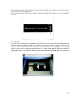

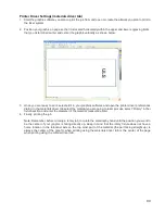


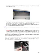


Beam Window
The Beam Window (1) is located where the laser beam enters into the processing area. It is located in the
upper left hand corner of the engraving area against the back wall and is yellow in color. It is only necessary
to clean the front side of the beam window. Do not remove the optic to clean it; simply clean it in the same
manner as the #2 mirror.
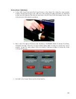
Cooling Fan Filters
The side (1) and rear (2) cooling fan filters are located inside the Rear Cover. To access them, remove the
two mounting screws (3) underneath the rear of the system. Lift the cover straight up and off. Locate the filters
on the inside of the rear cover and on the inside of the side vent panel. Remove the plastic retainers and the
filter media. Rinse the filter media with soap and water. Allow them dry before re-installing.
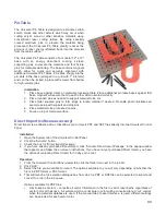
Exhaust Plenum
The exhaust plenum should be routinely inspected and cleaned to ensure good exhaust flow. To access the inside
of the exhaust plenum, lower the engraving table to the bottom of its travel and remove then remove the table by
loosening the thumbscrews on the right side and lifting the table out. You can then remove the exhaust plenum
cover on the inside back wall of the machine by gently pulling on it. It is held in place by snap fasteners. Clean the
inside of the plenum with a mild soap solution and then reinstall everything in the reverse order.
Adjustments and Lubrication
Periodic adjustments are not normally required. The bearings in the motion system will self-adjust to take up any
clearances as they begin to wear. The belts are fiber-reinforced and will not stretch under normal use so periodic
tension adjustment is not necessary. All bearings in the system are sealed and do not require lubrication. Do not
lubricate the tracks that the bearings ride in.
97
Summary of Contents for VLS2.30
Page 1: ...VLS Desktop User Guide VLS2 30 VLS3 50 www ulsinc com Revision 2012 08...
Page 5: ...Chapter 1 Specifications 5...
Page 8: ...Chapter 2 Safety 8...
Page 9: ......
Page 15: ......
Page 16: ......
Page 19: ...Chapter 3 Installation 19...
Page 36: ...Chapter 4 Operation 36...
Page 62: ......
Page 68: ...Chapter 5 Accessories 68...
Page 80: ...Example Connection for PNP mode Example Connection for NPN mode 80...
Page 92: ...Chapter 6 Maintenance 92...
Page 99: ...www ulsinc com...


