


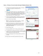
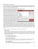

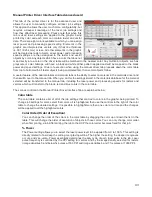


Step 3 – Printing to the Laser System (Using the Materials Database Tab)
1. Verify that the Universal Control Panel (UCP) is running in
the taskbar by looking for the square red icon.
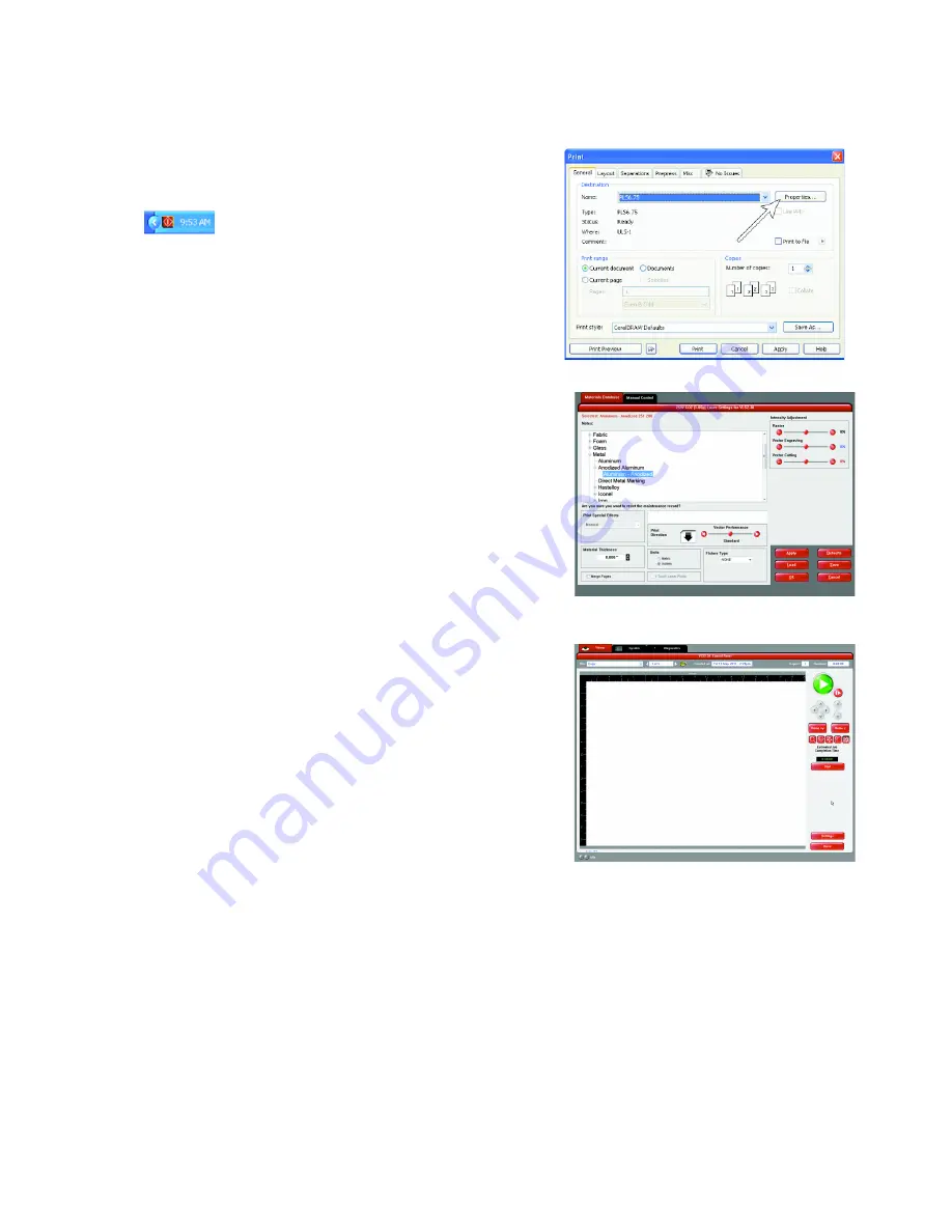
2. When you are ready to print the job, select PRINT from the
CorelDRAW FILE menu. Make sure that your laser system
printer driver appears in the DESTINATION NAME dropdown
list, and then click PROPERTIES (Figure 4) to display your
laser system printer driver settings (Figure 5).
3. Choose your material category, in this case metal, and then
select the desired material: Aluminum Anodized (Figure 5).
4. Set the Fixture Type to NONE.
Note:
If you were using an optional accessory or custom
fixture, you would choose it from the fixture list.
5. Measure the thickness of the material (a digital calipers is
recommended for this task) and enter it into the material
thickness field. In this example, the provided test card is
0.019” (0.483 mm) thick.
6. Select OK when done.
7. Now Select PRINT in the Print dialog window (Figure 4).
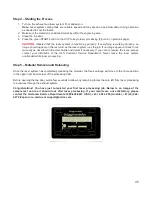
8. Launch the UCP by selecting the square red UCP icon on the
taskbar and the current print job will appear in the Viewer Tab
of the Universal Control Panel (Figure 6).
9. Now select the System Tab and verify that the Auto Z box is
checked.
10. Return to the Viewer Tab and proceed to the next step.
34
Figure 5
Figure 6
Figure 4
Summary of Contents for VLS2.30
Page 1: ...VLS Desktop User Guide VLS2 30 VLS3 50 www ulsinc com Revision 2012 08...
Page 5: ...Chapter 1 Specifications 5...
Page 8: ...Chapter 2 Safety 8...
Page 9: ......
Page 15: ......
Page 16: ......
Page 19: ...Chapter 3 Installation 19...
Page 36: ...Chapter 4 Operation 36...
Page 62: ......
Page 68: ...Chapter 5 Accessories 68...
Page 80: ...Example Connection for PNP mode Example Connection for NPN mode 80...
Page 92: ...Chapter 6 Maintenance 92...
Page 99: ...www ulsinc com...


