background image

Installation, Operation and Maintenance Manual

VariCool EZ-Fit

4

Subject to change without notice.

Wiring Diagram 

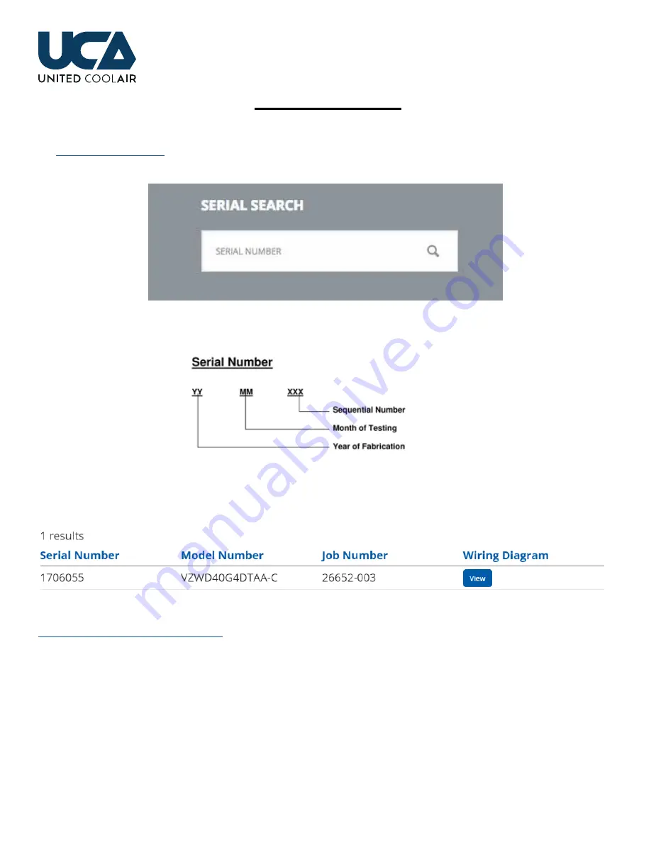
To retrieve the unit wiring diagram, scan the wiring diagram QR Code label affixed near the unit data tag  This will link to 

the 

wwwunitedcoolaircom

 website  Scroll down to the Serial Search box and enter the unit serial number

The serial number is a combination of the year, month and sequential order of build date

This will return the Model Number, Job Number and the Wiring Diagram for viewing as well as downloading

Wiring  diagrams  are  available  for  units  shipped  since  November  2016    For  older  units,  please  contact  the  factory  at  

wwwunitedcoolaircom/general-inquiry/

.

Summary of Contents for VariCool EZ-Fit Series

Page 1: ...VariCool EZ Fit Series Installation Operation and Maintenance Manual Effective March 2023 Variable Air Volume Water Cooled Water Source Heat Pump...

Page 2: ......

Page 3: ...ments 19 Water Piping 20 Electrical and Controls 21 Power Wiring 21 Transformer 22 Voltage Unbalance 22 High Duct Static Pressure Switch 22 Low Voltage Control Devices 22 Wall Display 22 BMS Applicati...

Page 4: ...w unitedcoolair com website Scroll down to the Serial Search box and enter the unit serial number The serial number is a combination of the year month and sequential order of build date This will retu...

Page 5: ...s IMPORTANT and INFORMATION will be used in areas where there is important information but not hazard related These instructions local codes and ordinances and applicable standards that apply to pipin...

Page 6: ...litate handling most units or modules are shipped on a wooden skid Use caution when moving the unit or modules so that damage does not occur when moving each piece to the final installation location w...

Page 7: ...apply to all air path configurations b Service clearances apply to all size units SERVICE ACCESS TOP VIEW Additional Clearance required for ECM DDP Fans Only SERVICE ACCESS SERVICE ACCESS FILTER ACCES...

Page 8: ...fficient depth in water column to permit the condensate to flow from the drain pan Failure to have a sufficient drain trap will cause the condensate to overflow the drain pan or to cause the unit to s...

Page 9: ...5 3 6 14x24 25x25 6 14 2 27 Dual Module Nominal Tons Blower Type Filter Size Evap Coil Compressor R 410A ECM iDDP DWDI Qty Size in Rows FPI Qty Lbs Ckt 30 8 4 15x20 20x20 4 14 4 7 40 12 18x25 4 14 4 1...

Page 10: ...8 6280 6280 N A 35 77 1 2 60 1 8 105 1 8 3660 3780 N A 70 153 58 5 8 105 1 8 7320 7560 N A 40 45 77 59 1 2 112 4220 4350 N A 80 90 152 1 2 58 112 8440 8700 N A Single Module Nominal Tons Condensing Se...

Page 11: ...8 3 4 60 1 8 34 460 80 90 2 77 34 1 2 78 1850 2 77 25 78 1450 4 38 1 2 59 1 2 34 460 1 Dimension in includes hardware 2 Dimension in does not include depth of removeable Filter Rack Filter rack depth...

Page 12: ...notice that the middle beam supports the mid section of the unit Field supplied spring vibration isolators are to be installed on each corner of each frame per module 2 Channel Steel with Waffle Pads...

Page 13: ...Z Fit 13 Subject to change without notice Figure 3C Base Option 2 Channel Steel with Waffle Pads Bottom View Figure 3D Base Option 2 Unit View Single Module Figure 3F Base Option Unit View Single Modu...

Page 14: ...ide opposite the filters Each section is also alphabetically labeled so that each section can be mated properly Set the sections so that point A aligns to A B aligns to B C aligns to C Evaporator Sect...

Page 15: ...flow between the evaporator and compressor condensing section For shipping purposes the refrigerant fittings are held in place to the cabinet using vinyl coated hangers and a mounting bracket These a...

Page 16: ...they ensure perfect alignment of the mating section surfaces Once adjacent sections have been put into place use the included hardware to pull sections together until the curved surfaces of the 3D Int...

Page 17: ...Installation Operation and Maintenance Manual VariCool EZ Fit 17 Subject to change without notice Figure 5A Single Module TYPICAL 8 PLACES...

Page 18: ...Installation Operation and Maintenance Manual VariCool EZ Fit 18 Subject to change without notice Figure 5B Dual Module TYPICAL 16 PLACES...

Page 19: ...or local codes Typically these units are installed using the mechanical room as the return air plenum However return ductwork can be applied Sufficient duct flange area exists on the filter frame for...

Page 20: ...in case temperature approaches too close to the freezing point INFORMATION Do not reduce the water inlet or outlet connection size as this will restrict water flow and increase water pressure drop CA...

Page 21: ...accordance with NEC National Electrical Code and NFPA National Fire Protection Agency most current versions as well as any applicable state or local codes INFORMATION The correct phase sequence of th...

Page 22: ...ted and resolved for the unit power supply the building manager or owner should be notified of the issue to get the proper power supplied to the unit High Duct Static Pressure Switch A high duct stati...

Page 23: ...lled shipped loose item The return air temp sensor should be placed in an area that can properly average all of the return air preferably right before the filters if possible For maintenance room plen...

Page 24: ...pipe feeding condenser water to the unit A reduction of water flow from the unit head pressure control valve operation may cause nuisance trips Water flow switch trips will cause loss of water flow al...

Page 25: ...jury CAUTION Any maintenance should be conducted by qualified HVAC service personnel only Potentially hazardous situations may result in personal injury equipment or property damage Lubrication Belt D...

Page 26: ...nsioning below Figure 8 Belt Tensioning For proper tensioning use the following equation Deflection Belt Span 64 Belt span is in inches from center pulley to center pulley see Figure 8 Belt tension is...

Page 27: ...higher operating costs or occupant discomfort The finned coils in a unit should be checked at least every six 6 months or more frequently based on experience of the specific application Before cleani...

Page 28: ...rigerant system glass If the color of this indicator is green or blue the refrigerant is normal When the indicator is yellow an abnormal condition exists such as moisture within the refrigerant circui...

Page 29: ...operating parameters to obtain the CFM 3 Water balance verification Ensure that the unit has 3 gpm per ton available to it at all times if a pump is of variable speed it must be able to ramp up its sp...

Page 30: ...enser 5 Resolve incoming voltage issue 6 Resolve alarm condition Note Compressor internal overload may require an extended period of time 1 hour or more to reset Compressor short cycles 1 Reduced air...

Page 31: ...mal expansion valve bulb is tight on suction line 5 Confirm thermal expansion valve bulb is located properly on suction line 6 Replace thermal expansion valve 7 Replace filter drier 8 Check filters an...

Page 32: ...rly 2 Control wiring issue 3 Controls in an alarm condition 4 High or low pressure switch open 5 Compressor thermal overload open 1 Turn on and set controller for desired operation 2 Check wiring conn...

Page 33: ...es due to i failure to install operate or maintain deliverables as directed in any instruction manual provided or under applicable law or regulation ii misuse abuse neglect or modification of a delive...

Page 34: ...eliverable by Seller whichever occurs first Except as set forth in these terms Seller makes no representation or warranty of any type express or implied including any warranty of merchantability warra...

Page 35: ...been adjusted to the voltage being applied Yes No 11 Has overcurrent protection breakers fuses been installed to match the unit nameplate requirement Yes No 12 Do all fans rotate freely Yes No 13 Does...

Page 36: ...in the correct direction three phase units only NOTE If the evaporator blower motor runs backwards shut off all power to the unit Switch any two of the incoming power leads at the unit main power ter...

Page 37: ...nce between the liquid line temperature and the saturation temperature corresponding to the liquid line pressure 11 Record the Amps for the evaporator blower motor and each compressor If the system is...

Page 38: ...lters are in place clean usable Yes ____________ No ____________ Three Phase Measured Voltage L1 L2_____________ L2 L3_ ____________ L1 L3__________ Evaporator Blower Motor Rotation OK Yes ___________...

Page 39: ...________ Suction Superheat _ ________ _ ________ _ ________ _ ________ Liquid Line Pressure psi________ psi________ psi________ psi________ Saturation Temperature Liquid Line Temperature F_________ F_...

Page 40: ...in Tons Single Module 30 40 50 60 70 80 or 90 Nominal Cooling Capacity in Tons Dual Module e G Common to all f 3 208 230 3 60 4 460 3 60 g A Two Compressors D Four Compressors h T Traditional Cabinet...

Page 41: ...7 00 PM Eastern Standard Time Saturday 8 00 AM 4 00 PM Call 717 843 4311 and Dial extension 165 This log must be kept with the unit It is the responsibility of the owner and or maintenance service con...

Page 42: ...Installation Operation and Maintenance Manual VariCool EZ Fit 42 Subject to change without notice NOTES...

Page 43: ...ITED WARRANTY United CoolAir Units are backed by a 1 year limited warranty on parts and a 5 year limited warranty on the compressor labor not included Maintenance items such as filters and belts are e...

Reviews: