


271001-UIM-A-0407
Unitary Products Group
3
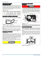
INSPECTION
As soon as a unit is received, it should be inspected for possible dam-
age during transit. If damage is evident, the extent of the damage
should be noted on the carrier’s freight bill. A separate request for
inspection by the carrier’s agent should be made in writing. Also, before
installation the unit should be checked for screws or bolts, which may
have loosened in transit. There are no shipping or spacer brackets
which need to be removed.
FURNACE LOCATION AND CLEARANCES
The furnace shall be located using the following guidelines:
1.
Where a minimum amount of air intake/vent piping and elbows will
be required.
2.
As centralized with the air distribution as possible.
3.
Where adequate combustion air will be available (particularly
when the appliance is not using outdoor combustion air).
4.
Where it will not interfere with proper air circulation in the confined
space.
5.
Where the outdoor vent terminal will not be blocked or restricted.
Refer to “VENT CLEARANCES” located in SECTION VII of these
instructions. These minimum clearances must be maintained in
the installation.
6.
Where the unit will be installed in a level position with no more
than 1/4” (6.4 mm) slope side-to-side and front-to-back.
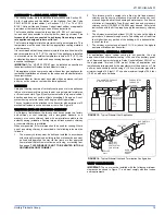
Installation in freezing temperatures:
1.
Furnace shall be installed in an area where ventilation facilities
provide for safe limits of ambient temperature under normal oper-
ating conditions. Ambient temperatures may fall below 32° F (0° C)
providing the flue temperature does not fall below 260° F (127° C)
at any point in the flue pipe between the furnace and the chimney
or a B-Vent. The flue products will condense in the vent pipe if the
flue temperature falls below 260° F (127° C) causing the vent pipe
to deteriorate rapidly.
2.
Do not allow return air temperature to be below 55º F (13° C) for
extended periods. To do so may cause condensation to occur in
the main heat exchanger, leading to premature heat exchanger
failure.
3.
If this furnace is installed in an unconditioned space and an
extended power failure occurs, there will be potential damage to
the internal components. Following a power failure situation, do
not operate the unit until inspection and repairs are performed.
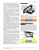
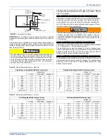
Clearances for access:
Ample clearances should be provided to permit easy access to the unit.
The following minimum clearances are recommended:
1.
Twenty-four (24) inches (61 cm) between the front of the furnace
and an adjacent wall or another appliance, when access is
required for servicing and cleaning.
2.
Eighteen (18) inches (46 cm) at the side where access is required
for passage to the front when servicing or for inspection or
replacement of flue/vent connections.
In all cases, accessibility clearances shall take precedence over clear-
ances for combustible materials where accessibility clearances are
greater.
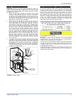
Installation in a residential garage:
A gas-fired furnace for installation in a residential garage must be
installed so the burner(s) and the ignition source are located not less
than 18 inches (46 cm) above the floor, and the furnace must be located
or protected to avoid physical damage by vehicles.
The furnace area must not be used as a broom closet or for any
other storage purposes, as a fire hazard may be created. Never
store items such as the following on, near, or in contact with the fur-
nace.
1. Spray or aerosol cans, rags, brooms, dust mops, vacuum
cleaners or other cleaning tools.
2. Soap powders, bleaches, waxes or other cleaning com-
pounds; plastic items or containers; gasoline, kerosene, ciga-
rette lighter fluid, dry cleaning fluids or other volatile fluid.
3. Paint thinners and other painting compounds.
4. Paper bags, boxes or other paper products
Never operate the furnace with the blower door removed. To
do so could result in serious personal injury and/or equipment
damage.
FOR FURNACES INSTALLED IN THE COMMON-
WEALTH OF MASSACHUSETTS ONLY
For all side wall horizontally vented gas fueled equipment installed in
every dwelling, building or structure used in whole or in part for resi-
dential purposes, including those owned or operated by the Com-
monwealth and where the side wall exhaust vent termination is less
than seven (7) feet above finished grade in the area of the venting,
including but not limited to decks and porches, the following require-
ments shall be satisfied:
1.
INSTALLATION OF CARBON MONOXIDE DETECTORS.
At
the time of installation of the side wall horizontal vented gas
fueled equipment, the installing plumber or gasfitter shall
observe that a hard wired carbon monoxide detector with an
alarm and battery back-up is installed on the floor level where
the gas equipment is to be installed. In addition, the installing
plumber or gasfitter shall observe that a battery operated or
hard wired carbon monoxide detector with an alarm is installed
on each additional level of the dwelling, building or structure
served by the side wall horizontal vented gas fueled equipment.
It shall be the responsibility of the property owner to secure the
services of qualified licensed professionals for the installation of
hard wired carbon monoxide detectors
a.
In the event that the side wall horizontally vented gas
fueled equipment is installed in a crawl space or an attic,
the hard wired carbon monoxide detector with alarm and
battery back-up may be installed on the next adjacent floor
level.
b.
In the event that the requirements of this subdivision can
not be met at the time of completion of installation, the
owner shall have a period of thirty (30) days to comply with
the above requirements; provided, however, that during
said thirty (30) day period, a battery operated carbon mon-
oxide detector with an alarm shall be installed.
2.
APPROVED CARBON MONOXIDE DETECTORS.
Each car-
bon monoxide detector as required in accordance with the
above provisions shall comply with NFPA 720 and be ANSI/UL
2034 listed and IAS certified.
3.
SIGNAGE.
A metal or plastic identification plate shall be perma-
nently mounted to the exterior of the building at a minimum
height of eight (8) feet above grade directly in line with the
exhaust vent terminal for the horizontally vented gas fueled
heating appliance or equipment. The sign shall read, in print
size no less than one-half (1/2) inch in size, "
GAS VENT
DIRECTLY BELOW. KEEP CLEAR OF ALL OBSTRUC-
TIONS
".
4.
INSPECTION.
The state or local gas inspector of the side wall
horizontally vented gas fueled equipment shall not approve the
installation unless, upon inspection, the inspector observes car-
bon monoxide detectors and signage installed in accordance
with the provisions of 248 CMR 5.08(2)(a)1 through 4.
Improper installation in an ambient below 32ºF (0.0° C) could create
a hazard, resulting in damage, injury or death.


