


271001-UIM-A-0407
24
Unitary Products Group
Continuous Blower Operation
The blower will run continuously whenever the wall thermostat fan
switch is in the "ON" position. The furnace blower will run at the speed
selected on the "FAN SPEED" jumpers on the main control board (HI
COOL, LO COOL, HI HEAT or LO HEAT). When the jumper is in the
"VS G" position, the blower will run at 50% of the high cool speed.
Intermittent Blower Cooling
On cooling/ heating thermostats with a fan switch, when the fan switch
is set in the auto position and the thermostat calls for cooling, a circuit is
completed between the R, Y and G terminals. The motor is energized
through the Y1 cool terminal and runs on the speed selected on the
control board. The fan-off setting is fixed at 60 seconds for SEER
enhancement.
Intermittent Blower Heating
On cooling/ heating thermostats with a fan switch, when the fan switch
is set in the auto position and the thermostat calls for heating, a circuit is
completed between the R and W terminals. The indoor fan motor is
energized through the W1or W2 heat terminal and runs on the “High
Heat or Low Heat “ speed selected on the control board.
Humidistat
When a humidistat is installed in the system, the “Humidistat Installed?”
jumper on the control board should be moved to the “YES” position. The
cooling CFM will then be reduced by 15% whenever the humidistat indi-
cates high humidity.
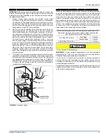
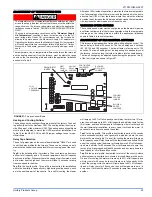
FURNACE CONTROL DIAGNOSTICS
The furnace has built-in, self-diagnostic capability. If a system problem
occurs, a blinking LED shows a fault code. The LED can flash red,
green or amber to indicate various conditions. It is located behind a
clear view port in the blower compartment door.
The control continuously monitors its own operation and the operation
of the system. If a failure occurs, the LED will indicate the failure code. If
the failure is internal to the control, the light will stay on continuously. In
this case, the entire control should be replaced, as the control is not
field repairable.
Flash sequence codes 1 through 10 are as follows: LED will turn “on”
for 1/4 second and “off” for 1/4 second. This pattern will be repeated the
number of times equal to the code. For example, six “on” flashes equals
a number 6 fault code. All flash code sequences are broken by a 2 sec-
ond “off” period.
SLOW GREEN FLASH:
Normal operation.
SLOW AMBER FLASH:
Normal operation with call for heat.
RAPID RED FLASH:
Twinning error, incorrect 24V phasing. Check
twinning wiring.
RAPID AMBER FLASH:
Flame sense current is below 1.5 microamps.
Check and clean flame sensor. Check for proper gas flow.
4
AMBER FLASHES:
The control board is recieving a “Y” signal from
the thermostat without a “G” signal, indicating improper thermostat wir-
ing.
1 RED FLASH:
This indicates that flame was sensed when there was
not a call for heat. With this fault code the control will turn on both the
inducer motor and supply air blower. A gas valve that leaks through or
is slow closing would typically cause this fault.
2 RED FLASHES:
This indicates that the normally open pressure
switch contacts are stuck in the closed position. The control confirms
these contacts are open at the beginning of each heat cycle. This would
indicate a faulty pressure switch or miswiring.
3 RED FLASHES:
This indicates the normally open pressure switch
contact did not close after the inducer was energized. This could be
caused by a number of problems: faulty inducer, blocked vent pipe, bro-
ken pressure switch hose or faulty pressure switch.
4 RED FLASHES:
This indicates that a primary or auxiliary limit switch
has opened its normally closed contacts. With this fault code the control
will operate the supply air blower and inducer. This condition may be
caused by: dirty filter, improperly sized duct system, incorrect blower
speed setting, incorrect firing rate or faulty blower motor.
5 RED FLASHES:
This fault is indicated if the normally closed contacts
in the rollout switch opens. The rollout control is manually reset. If it has
opened, check for proper combustion air, proper inducer operation, and
primary heat exchanger failure or burner problem. Be sure to reset the
switch after correcting the failure condition.
6 RED FLASHES:
This indicates that after the unit was operating, the
pressure switch opened 4 times during the call for heat. If the main
blower is in a “Delay on” mode it will complete it, and any subsequent
delay off period. The furnace will lock out for one hour and then restart.
7 RED FLASHES:
This fault code indicates that the flame could not be
established. This no-light condition occurred 3 times (2 retries) during
the call for heat before locking out. Low gas pressure, faulty gas valve,
faulty hot surface ignitor or burner problem may cause this. The furnace
will lock out for one hour and then restart.
8 RED FLASHES:
This fault is indicated if the flame is lost 5 times (4
recycles) during the heating cycle. This could be caused by low gas
pressure or faulty gas valve. The furnace will lock out for one hour and
then restart.
9 RED FLASHES:
Indicates reversed line voltage polarity or grounding
problem. Both heating and cooling operations will be affected. Check
polarity at furnace and branch. Check furnace grounding. Check that
flame probe is not shorted to chassis.
10 RED FLASHES:
Gas valve energized with no call for heat. Check
gas valve and gas valve wiring.
11 RED FLASHES:
This indicates that a primary or auxiliary limit switch
has opened its normally-closed contacts and has remained open for
more than five minutes. This condition is usually caused by a failed
blower motor or blower wheel.
12 RED FLASHES:
This code indicates an open igniter circuit, which
could be caused by a disconnected or loose wire or by a cracked or bro-
ken igniter.
STEADY ON RED:
Control failure. Replace control board.
60-MINUTE AUTOMATIC RESET FROM LOCKOUT:
This control
includes a “watchdog” type circuit that will reset from a lockout condition
after 60 minutes. Operational faults 6,7,8 will be reset. This provides
protection to an unoccupied structure if a temporary condition exists
causing a furnace malfunction. An example would be a low incoming
gas supply pressure preventing unit operation. When the gas pressure
is restored, at some point the “watchdog” would restart the unit and pro-
vide heat for the house.
NOTE:
If a flame is detected the control flashes the LED for 1/8 of a
second and then enters a flame stabilization period.
IGNITION CONTROL
Normal flame sense current is approximately
3.7 microamps DC (µa)
Low flame signal warning starts at 1.5 microamps.
Low flame signal control lockout point is
0.1 microamps DC (µa)


