Unitary products group AHV8 UH Installation Manual Download Page 10

271001-UIM-A-0407

10

Unitary Products Group

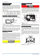
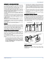
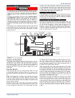
SECTION V: ELECTRICAL POWER

Electrical Power Connections

Field wiring to the unit must be grounded. Electric wires that are field
installed shall conform to the temperature limitation of 63°F (35°C) rise
when installed in accordance with these instructions. Refer to Table 8 in
these instructions for specific furnace electrical data.

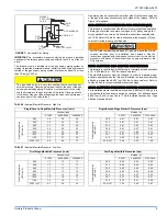
1. Annual Fuel Utilization Efficiency (AFUE) numbers are determined in accordance with DOE Test procedures.
2. Field wiring and over-current protection (Max Fuse Size) must conform to and be grounded in accordance ANSI/NFPA 

No. 70-latest edition or the Canadian Electrical Code C222.1 Part 1-latest edition and / or local codes.

3. Wire size based on copper conductors, 60º C, 3% voltage drop. "Unit Amps" refers to the full load current.
4. Min wire size (awg) @ 75 ft. one way refers to the minimum recommended field installed wire size.

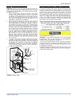
PROPANE AND HIGH ALTITUDE CONVERSION KITS
It is very important to choose the correct kit and/or gas orifices for the altitude and the type of gas for which the furnace is being installed.
Only use natural gas in furnaces designed for natural gas. Only use propane (LP) gas for furnaces that have been properly converted to use pro-
pane (LP) gas. Do not use this furnace with butane gas.
Incorrect gas orifices or a furnace that has been improperly converted will create an extremely dangerous condition resulting in premature heat
exchanger failure, excessive sooting, high levels of carbon monoxide, personal injury, property damage, a fire hazard and/or death.
High altitude and propane (LP) conversions are required in order for the appliance to satisfactory meet the application.
An authorized distributor or dealer must make all gas conversions.
In Canada, a certified conversion station or other qualified agency, using factory specified and/or approved parts, must perform the conversion.
The installer must take every precaution to insure that the furnace has been converted to the proper gas orifice size when the furnace is installed.
Do not attempt to drill out any orifices to obtain the proper orifice size. Drilling out a gas orifice will cause misalignment of the burner flames,
causing premature heat exchanger burnout, high levels of carbon monoxide, excessive sooting, a fire hazard, personal injury, property damage
and/or death.

Use copper conductors only.
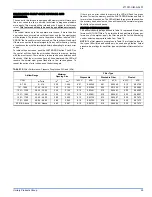
TABLE 8: 

Ratings & Physical / Electrical Data

Input

High/Low

Output BTU/H

High/Low

Nominal

Airflow

Cabinet Width

AFUE

Blower

Blower Size

MBH

kW

MBH

kW

CFM

m

3

/min

In

cm

Hp

Amps

In

cm

57/42

16.7/12.3

46/34

13.5/10.0

1200

34.0

14-1/2

36.8

80.0

1/2

7.7

10 x 8

25.4 x 20.3

80/59

23.4/17.3

64/48

18.8/14.1

1200

34.0

14 1/2

36.8

80.0

1/2

7.7

10 x 8

25.4 x 20.3

80/59

23.4/17.3

64/48

18.8/14.1

1600

45.3

17-1/2

44.5

80.0

3/4

9.6

10 x 10

25.4 x 25.4

80/59

23.4/17.3

64/48

18.8/14.1

1600

45.3

21

53.3

80.0

3/4

9.6

10 x 10

25.4 x 25.4

100/65

29.3/19.1

80/53

23.4/15.5

1600

45.3

17 1/2

44.5

80.0

3/4

9.6

10 x 10

25.4 x 25.4

100/65

29.3/19.1

80/53

23.4/15.5

1600

45.3

21

53.3

80.0

3/4

9.6

10 x 10

25.4 x 25.4

100/65

29.3/19.1

80/53

23.4/15.5

2000

56.6

21

53.3

80.0

1

12.8

11 x 10

27.9 x 25.4

120/78

35.1/22.9

96/64

28.1/18.8

2000

56.6

21

53.3

80.0

1

12.8

11 x 10

27.9 x 25.4

Input/Cabinet

High/Low

Max. Outlet Air 

Temp

Low Fire

Air Temp. Rise

High Fire

Air Temp. Rise

Unit 

Amps

Max 

Over-Current 

Protect

Min. wire Size 

(awg) @ 75 ft 

one way

Operation 

Weight

MBH

kW

°F

°C

°F

°C

°F

°C

Lbs

 Kg

57/42

16.7/12.3

165

73.9

25-55

14-31

35-65

19-36

9.0

20

14

107

48.5

80/52

23.4/17.3

170

76.7

30-60

17-33

40-70

22-39

9.0

20

14

117

43.7

80/59

23.4/17.3

155

68.3

25-55

14-31

25-55

14-31

12.0

20

14

129

58.5

80/59

23.4/17.3

155

68.3

25-55

14-31

25-55

14-31

12.0

20

14

140

63.5

100/65

29.3/19.1

170

76.7

25-55

14-31

40-70

22-39

12.0

20

14

128

47.8

100/65

29.3/19.1

170

76.7

25-55

14-31

40-70

22-39

12.0

20

14

140

63.5

100/65

29.3/19.1

170

76.7

25-55

14-31

40-70

22-39

14.0

20

12

145

54.1

120/78

35.1/22.9

165

73.9

25-55

14-31

35-65

19-36

14.0

20

12

147

54.9

Summary of Contents for AHV8 UH

Page 1: ...ited to building electrical and mechanical codes LIST OF SECTIONS SAFETY 1 DUCTWORK 4 FILTERS 8 GAS PIPING 8 ELECTRICAL POWER 10 VENT SYSTEM 14 SAFETY CONTROLS 19 START UP AND ADJUSTMENTS 20 WIRING DI...

Page 2: ...s from combustible materials as listed under Clearances to Combustibles in Table 1 Provide clearances for servicing ensuring that service access is allowed for both the burners and blower These models...

Page 3: ...ed Never store items such as the following on near or in contact with the fur nace 1 Spray or aerosol cans rags brooms dust mops vacuum cleaners or other cleaning tools 2 Soap powders bleaches waxes o...

Page 4: ...erates at the specified external static pressure and within the air temperature rise specified on the nameplate Table 2 is a guide for determining whether the rectangular duct system that the furnace...

Page 5: ...supply plenum On all installations without a coil a removable access panel is recommended in the outlet duct such that smoke or reflected light would be observable inside the casing to indi cate the...

Page 6: ...floor support with required service accessibility IMPORTANT If an external mounted filter rack is being used see the instructions provided with that accessory for proper hole cut size HORIZONTAL MODEL...

Page 7: ...removed and a new plenum installed that is the proper size for the new furnace Attach the return plenum to the furnace inlet duct flanges This is typi cally through the use of S cleat material when a...

Page 8: ...IV GAS PIPING GAS SAFETY IMPORTANT Plan your gas supply before determining the correct gas pipe entry Use 90 degree service elbow s or short nipples and con ventional 90 degree elbow s to enter throu...

Page 9: ...ing The gas valve body is a very thin casting that cannot take any external pressure Never apply a pipe wrench to the body of the gas valve when installing piping A wrench must be placed on the octag...

Page 10: ...er must take every precaution to insure that the furnace has been converted to the proper gas orifice size when the furnace is installed Do not attempt to drill out any orifices to obtain the proper o...

Page 11: ...ty is corrected Refer to FURNACE DIAGNOSTICS section of the User s Information Maintenance Service Manual provided with this furnace for symptoms of reversed power supply polarity LOW VOLTAGE CONTROL...

Page 12: ...Stage Cool Y2 Second Stage Cool W2 Second Stage Heat G Fan R 24 Volt Hot W First Stage Heat Y1 First Stage Cool R 24 Volt Hot Y Y2 Single Second Stage Cool Y2 Second Stage Cool W2 Second Stage Heat G...

Page 13: ...versing Valve Energized in Cool O Reversing Valve Energized in Cool O Reversing Valve Energized in Cool Y2 Second Stage Heat Cool DHM Dehumidistat HUM Dehumidification Open on Humidity Rise Y2 Second...

Page 14: ...ssory Connections FIGURE 12 Vent Termination 115 VOLT HUMIDIFER 115 VOLT ELECTRONIC AIR CLEANER EAC HOT HUM HOT BLK WHT EAC HUM NEUTRALS SWITCHED CIRCUITS BLK WHT LOWEST DISCHARGE OPENING LISTED CAP L...

Page 15: ...the authority having jurisdiction Venting into an unlined masonry chimney or concrete chimney is prohibited Whenever possible B 1 metal pipe should be used for venting Where use of an existing chimne...

Page 16: ...nd from any direction will not create a positive pressure in the vicinity of the vent FIGURE 17 Home Layout L E D B V V V X V B V J X B B B V V F V C B X V I V G H A M K OPERABLE FIXED CLOSED VENT TER...

Page 17: ...obtain proper air for combus tion and ventilation in confined spaces Combustion Air Source From Outdoors The blocking effects of louvers grilles and screens must be given con sideration in calculatin...

Page 18: ...el of the appliance Refer to COMBUSTION AIR SOURCE FROM OUTDOORS and VENT AND SUPPLY AIR SAFETY CHECK in these instructions for additional information and safety check procedure 2 The duct shall be ei...

Page 19: ...ustion air blower heat exchanger or a blocked vent pipe connection Corrective action is required These are manual reset controls that must be reset before operation can continue PRESSURE SWITCHES This...

Page 20: ...in w c 0 3 73 kPa in order to measure the gas line and the manifold pressures 4 You will need a 3 32 Allen wrench for the pressure port plugs in the gas valve 5 You will need 2 pieces of 1 8 0 3 cm ID...

Page 21: ...at the gas meter times a barometric pressure and temperature correction factor of 0 960 times 3600 then divided by the time it took to measure 0 10 m3 of gas from the gas meter For Propane LP Gas mul...

Page 22: ...h low and high have been calibrated at the factory Additional pressure adjustment should not be necessary If adjustment is necessary set to the following specifications After adjustment check for gas...

Page 23: ...eed to the other Tap B is the humid profile This profile is best suited for installations where the humidity is frequently very high during cooling season such as in the southern part of the country O...

Page 24: ...pressure switch or miswiring 3 RED FLASHES This indicates the normally open pressure switch contact did not close after the inducer was energized This could be caused by a number of problems faulty i...

Page 25: ...ry the LED will flash two green flashes To clear the memory push the LAST ERROR button and hold it for more than five seconds The LED will flash three green flashes when the memory has been cleared th...

Page 26: ...47 5 30 9 47 5 30 9 1540 1001 1540 1001 C B 43 6 28 3 43 6 28 3 1440 936 1440 936 B C 40 8 26 5 40 8 26 5 1320 858 1320 858 D B 37 4 24 3 37 4 24 3 1400 910 1400 910 C A 39 6 25 8 39 6 25 8 1200 780 1...

Page 27: ...stem static from 0 60 w c 150 Pa and divide this by 0 1 w c 25 Pa 0 68 170 Pa 0 60 150 Pa 0 08 20 Pa 0 08 20 Pa 0 1 25 Pa 0 8 Multiply this by 2 to obtain the percentage reduction in airflow 0 8 x 0 0...

Page 28: ...Printed in U S A 271001 UIM A 0407 Copyright by York International Corp 2007 All rights reserved Supersedes 167187 UIM C 0806 Unitary 5005 Norman Product York OK Group Drive 73069 SECTION IX WIRING D...

Reviews: