


271001-UIM-A-0407
Unitary Products Group
13
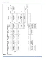
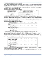
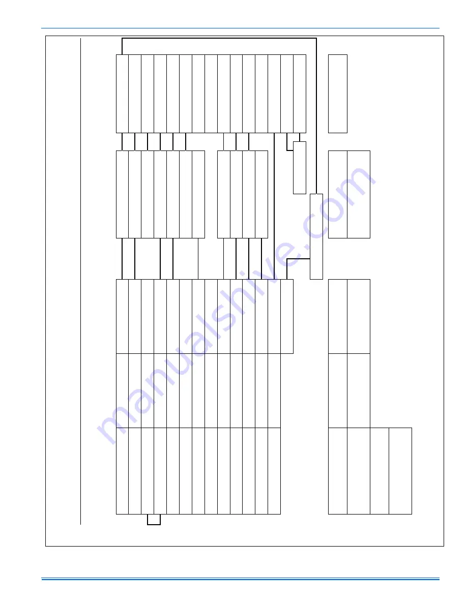
FIGURE 10:
Thermostat Chart - HP
HP24
Two Stage H/P - H*5B, YZE - w/Variable 2 Stage Furnace, 2 Stage Cooling Ready - PV8/9, (F,L)*8/9V, (G,L)*8/9V, XYG80V-U, XY
F80V-U / XYF80V-U*L
W/031-01996- Series Demand Control; Hot Heat Pump Mode OR Conventional
TWO STAGE
HEAT PUMP
*PP32U70124
*DN22H00124
*PP32U71124
THERMOSTAT THERMOSTAT
THERMOSTAT
VARIABLE SPEED
FURNACE CONTROL
*DP22U70124
*PP32U72124
C
24-Volt Common
C
24-Volt Common
C
24-Volt Common
C
24-Volt Common
C
24-Volt Common
Y
First Stage Heat/Cool
Y1
First Stage Heat/Cool
Y1
First Stage Heat/Cool
Y1
First Stage Cool
Y1
First Stage Heat/Cool
Y2 OUT
Second Stage Cool Output
R
24-Volt Hot (Heat XFMR)
R
24-Volt Hot
R
24-Volt Hot
R
24-Volt Hot
R
24-Volt Hot
RC
24-Volt Hot (Cool XFMR)
Y/Y2
Single/Second Stage Cool
W1 OUT
First Stage Auxiliary Heat Output
W2
Second Stage Auxiliary Heat
W2
Second Stage Auxiliary Heat
W2
Second Stage Heat
W2 OUT
Second Stage Auxiliary Heat Output
E
Emergency Heat
W/W1
Single/First Stage Heat
G
Fan
G
Fan
G
Fan
G
Fan
CFM CONTROL
O
Reversing Valve–Energized in Cool
L
Malfunction Light
L
Malfunction Light
L
Malfunction Light
(X/L)
Malfunction Light
X/L
Malfunction Light
O/B
Reversing Valve
O
Reversing Valve–Energized in Cool
O
Reversing Valve–Energized in Cool
(O)
Reversing Valve–Energized in Cool
Y2
Second Stage Heat/Cool
DHM
Dehumidistat
HUM
Dehumidification - Open on Humidity Rise
Y2
Second Stage Heat/Cool
Y2
Second Stage Heat/Cool
Y2
Second Stage Heat/Cool
(Y 2)
AUX
Auxiliary Heat
E/W1
First Stage Auxiliary Heat
E/W1
First Stage Auxiliary Heat
W
Auxiliary Heat
HM
Humidistat
BSG
Bonnet Sensor
Bonnet Sensor (Optional)
BS
Bonnet Sensor
24V HUMIDIFIER
(Optional)
Thermostat Installer Setup Number 0170 -
System Type - must be set to
12 - 3 Heat/2 Cool Heat Pump
Selection of GAS/ELEC switch
on thermostat not necessary
Step 1 of Thermostat User Configuration
Menu must be set to Heat Pump 2
Set W2 Delay on furnace to OFF
Thermostat Installer Setup Number 0200 -
Backup Heat Source - must be set to 1 - Heat
Pump Backup Heat Source is Fossil Fuel
Thermostat Installer Setup Number 0210 -
External Fossil Fuel Kit - must be set to 0 -
External Fossil Fuel Kit is Controlling Heat
Pump Backup Heat
Change FFuel Jumper on
Heat Pump to ON
Thermostat Installer Setup Number 0190 -
Reversing Valve (O/B) Operation - must be
set to 0 - O/B Terminal Energized in Cooling
Step 1 of Thermostat User
Configuration Menu must be
set to Heat Pump 2
E2/P Switch must be in the E2 position
and the Humidistat Jumper on CFM
Control must be in the 'YES' position for
Dehumidification
( ) CONVENIENCE TERMINAL. NO
FUNCTION IN THIS APPLICATION.


