Page 9 of 39
Rev. 13
1.4.6 Configuring the PCOM board
Once the
PCOM
board is properly connected, it needs to be configured to operate on the network or with the host
system that it is connected to. As already mentioned, the board is factory-configured for DHCP operation; it should
automatically acquire an IP address on DHCP-enabled networks and be available for immediate use. If your
PCOM
board is connected to a network without DHCP support, you will need to assign an IP address to the board. Follow the
directions in
Section “Configuring the PCOM board’s IP Address”.
1.4.6.1 Configuring the PCOM board IP Address
By default, the
PCOM
board uses serial configuration to assign a permanent IP address to the board. The IP
configuration is written to the board’s EEPROM using a direct serial connection between the board and a host system.
To configure the
PCOM
board through the serial port:
1. From the Start menu, select
Programs > Accessories> Communications > HyperTerminal.
2. At the initial “Connection description” dialog box, enter a name for the connection. You may call the terminal session
any name that you can easily remember. Click
OK
.
3. At the “Connect To” dialog box that follows, choose the appropriate COM port from the drop-down menu. Click
OK
.
4. At the “COM Properties” dialog box that follows, select the following settings:
Bits per second:
19200
Data bits:
8
Parity:
none
Stop bits:
1
Flow Control:
none
Click
OK
. The Terminal window opens with a flashing cursor. The message, “Connected”, appears in the status bar at
the bottom of the Terminal window, along with an elapsed time display.
5. From the menu bar, select
Files>Properties
, then the
Settings
tab on the “Properties Dialog”. Click on the
ASCII
Setup
button and check the
Echo typed characters locally
check box in the following dialog box. Click on
OK
to exit
the dialog, and then
OK
to exit the “Properties Dialog”.
6. In the
PCOM
board configure the switch “BAUD RATE” (Figure 6) and restart
PCOM
board.
on
1
BAUD RATE
SW2
Figure 6
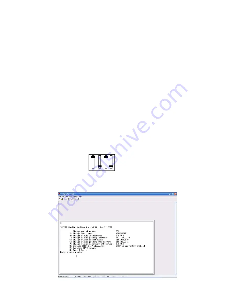
The terminal responds with the serial configuration menu: Figure 7 (values shown below are given as example).
Figure 7
Summary of Contents for ARR-M Series
Page 2: ... i BATTERY CHARGER USER S MANUAL ...
Page 5: ... iv FIGURE LIST 86 ACRONYM LIST 88 LCD MESSAGES LIST 90 APPENDIXES 92 ...
Page 6: ...MCEnPC23 REV 2 4 Page 1 PART 1 INSTALLATION INSTALLATION ...
Page 10: ...MCEnPC23 REV 2 4 Page 5 PART 2 THEORY OF OPERATION THEORYOFOPERATION ...
Page 98: ...Page 1 of 39 Rev 13 Communication User Manual Appendix 3 27 01 2015 ...