


USSI Microlok II Functional description
Page 24 of 27 July 2005 UM-6800A Rev1.3
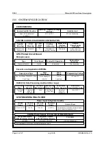
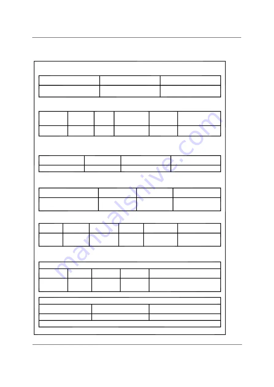
11.1. SYSTEM SPECIFICATION
RAM (Vital Data Processing and Event/Error Logs)
Data Batt. Back-Up
Event/Error
>4hrs. @25°C
Type
Vital Data:
Capacity
Vital Data:
Batt. Back-Up
Vital Data:
Data: Type
Event/Error
Event/Error
Data: Capacity
4 banks of
Low Power
None
2 banks of
Fast Static
64K x 16
RAM
Static Ram
512K x 16
(256K bytes)
(128K bytes)
19
Total
PCB
SYSTEM CARDFILE HARDWARE CONFIGURATION
Cardfile
Eurocard
PCB
Mounting
Mounting
Std. 19" rack,
Shelf or wall
Interface
Upper PCB
Slot Bus
Addressing
Slots
Connectors
Connector
Power Supply
Remote
connector housings
Via jumpers in
96-pin male
8-way screw lock
discrete wire conn.
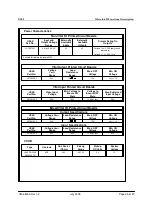
Operating Temperature Range
1.0grms, 0.2" displacement,
System Cardfile Vibration
ENVIRONMENTAL
5-1000 Hz
Humidity Limit
95% non-condensing
-40°C to +70°C
(All Units)
CPU Printed Circuit Board
Up to 8 megabytes
Executive and Application EPROMs
21 MHz
Clock Speed
Four Intel/Micron TE28F800CV-B90
Flash Type
Capacity and Type
Motorola MC68332
Microprocessor
Type
Operations
(4M x 16)
1 wait state
Total
Code Space
Clock
Speed
21 MHz
32 bits wide
+5V and +12V
Programming Voltage
16 or 8 bits wide
Internal Bit Operations
External Bus
*Not used to power vital or non-vital external devices or circuits
PCB 12V Internal Circuits
For System Cardfile
+12V @ 1A, -12V @ 1A
Cardfile Power Supply Printed Circuit Board Outputs*
11.5V DC
Min. Sys.
Start-Up
Power Input to System Cardfile
SYSTEM OPERATING POWER
For System Cardfile
PCB 5V Internal Circuits
+5V @ 3A
9.5 to 16.5V DC
Nominal
Voltage
Range
Voltage
12V DC
+12V into 400 ohm coil
TO VCOR
lamps, cab carrier frequency, etc.)
Determined by installation (number of signal
0.5V P-P
Maximum
Ripple
Current Draw


