


USSI Microlok II Functional description
Page 8 of 27 July 2005 UM-6800A Rev1.3
CPU Function
•
Monitoring external inputs from vital input boards and non-vital input
boards
•
Processing vital external inputs and executing logic defined in the
application software
•
Driving vital output boards as required by the application program
•
Monitoring and controlling serial communication ports (links to other
controllers)
•
Testing individual vital input and output channels for faults (in parallel
with control of these channels) and responding to detected faults
•
Monitoring system internal operation for faults and responding to detected
faults
•
Controlling power to vital outputs through the card file power supply and
an external VCOR (fail-safe function)
•
Recording system faults and routine events in user-accessible memory
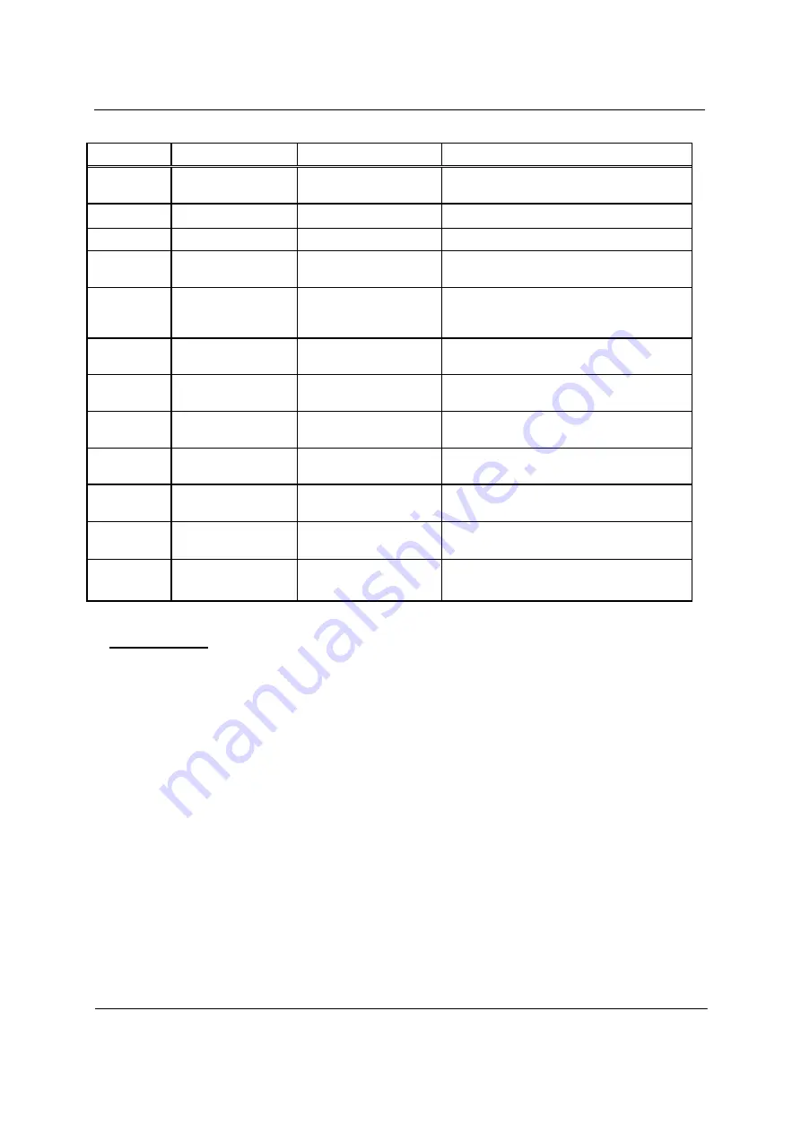
Fig. 2 Ref
Label
Device
Purpose
1, 2
(None)
4-character alpha-
numeric displays
On-site configuration programming menus
and options.
3
A, B, C, D, E
Yellow LEDs
Reserved for serial link status.
4
1, 2, 3, 4, 5, 6, 7, 8
Red LEDs
User-defined in application software.
5
ON LINE
Green LED
When lit, indicates normal system operation
(successful diagnostics).
6
VPP ON
Yellow LED
When lit, indicates FLASH +5V or +12V
programming voltage enabled (via board
jumper).
7
RESET
Green LED
When lit, indicates that the system is in reset
mode.
8
RESET
Momentary pushbutton
When pressed, resets the CPU. Also used to
place the CPU in the reset mode.
9
MENU L-R
3-position (return-to-
center) toggle switch
Used to search main program menu items
shown on displays.
10
MENU UP-DOWN
3-position (return-to-
center) toggle switch
Used to select main program menu items
shown on displays.
11
ADJUST UP-DOWN
3-position (return-to-
center) toggle switch
Used to cycle through configuration values to
be selected with
“ACTION”
switch.
12
ACTION ACCEPT-
REJECT
3-position (return-to-
center) toggle switch
Executes or cancels configuration value
selected with
“ADJUST”
switch.
13
RS-232 DTE
Diagnostic Link
Connector
DB9, RS-232 Connector
(DTE)
Used for connection to Maintenance PC for
System monitoring diagnosis.


