36
MaxTme-
Stage
1...63 min
Service
3 min
Cold start thermal
shock protection,
maximum time per
step (multistage)
ThresholdOff
1...100% Wcurrent
Service
80%
Cold start thermal
shock protection deac-
tivation level referred
to the current setpoint
(Wcurrent)
Additional-
Sens
deactivated
Service
deactivated
Pt100
Pt1000
Ni1000
Select extra sensor for
cold start thermal
shock protection
Temp Cold-
Start
---
User
0…2000 °C
Display of temperature
acquired by extra sen-
sor for the cold start
thermal shock protec-
tion function
Setpoint Add-
Sensor
60 °C
Service
0...450 °C
Setpoint for extra sen-
sor for cold start ther-
mal shock protection
Release Sta-
ges
release
Service
no release/
release
Cold start thermal
shock protection load
step stage mode (mul-
tistage operation)
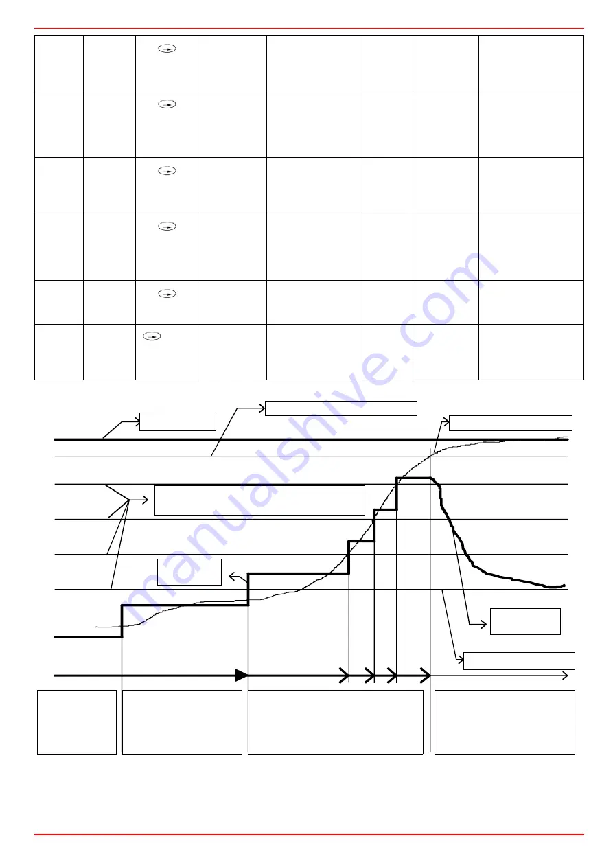
Spacing of temperature lines
corresponds to the setpoint steps
Manipulated
variable
Actual value
Setpoint
Threshold OFF
Threshold ON
Output
steps
7550d04E/0202
Setpoint step is reached
before max. time has elapsed.
Manipulated variable increased
by output step
Burner off,
actual value
below thresh-
old ON.
Burner will be
switched on
Setpoint step not reached,
but max. time exceeded.
Therefore, manipulated
variable increased by
output step
Actual value reached.
Threshold OFF
Change to control
Setpoint W1
Actual value
ThresholdOff
ThresholdOn
Burneroff, actual va-
lue below threshold
ON. Burner will be
switched on
Setpoint step not reached, but
max. time exceeded. Therefore,
manipulated variaile increased y
output step
Output Steps
Setpoint step is reached beforemax.time has
elapsed. Manipulated variabil increased by ou-
tput step
Actual value reached.
ThresholdOff
Change to control
Manipulated varia-
ble
Spacing of temperature lines corresponds to the setpoint
steps
Summary of Contents for P60 VS
Page 45: ...Service manual Siemens LMV 5x M12920CB Rev 1 08 2009...
Page 46: ......
Page 93: ......
Page 94: ......
Page 95: ......
Page 97: ...User manual Siemens LMV 5x M12914CA Rev 0 03 2008...
Page 98: ......
Page 109: ......
Page 110: ......
Page 111: ......
Page 114: ...Annex1 Example for motor cable...
Page 115: ......
Page 116: ...Annex 2 Example for sensor cable...
Page 117: ......
Page 118: ......
Page 122: ......


