C.I.B. UNIGAS - M03957CI
50
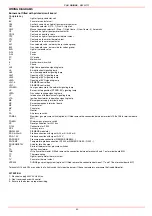
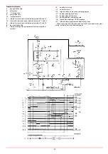
WIRING DIAGRAMS
Burners not fitted with printed circuit board
Complete key
BP
Light oil pump contactor coil
BV
Fan motor contactor coil
CAP
Auxiliary contacts on light oil pump motor contactor
CM
Operation selector 0) Off - 1) Gas - 2) Light oil
CMF
Manual operation selector 0) Stop - 1) High flame - 2) Low flame - 3) Automatic
CP
Contacts on light oil pump motor contactor
CR1/2
Contacts on auxiliary relais
CTP
Contacts on light oil pump motor thermal cutout
CTV
Contacts on fan motor thermal cutout
CV
Contacts on fan motor contactor
EV1
Gas solenoid valve, network side (or valves group)
EV2
Gas solenoid valve, burner side (or valves group)
EVG
Light oil solenoid valve
F÷F3
Fuses
F÷F4
Fuses
FC
UV probe
IG
Main switch
IL
Auxiliaries main switch
L
Phase
LAF
High flame operation signaling lamp
LB
Burner lockout signaling lamp
LBF
Low flame operation signaling lamp
LEV1
Opening of EV1 signaling lamp
LEV2
Opening of EV2 signaling lamp
LEVG
Opening of EVG signaling lamp
LFL1.3..
SIEMENS control box
LFL1...
SIEMENS control box
LPGMIN
Low gas pressure in the network signaling lamp
LS
Burner in stop position (STAND-BY) signaling lamp
LSPG
Gas valves leakage signaling lamp
LT
Intervention of thermal cutout signaling lamp
LTA
Ignition transformer in operation signaling lamp
MA
Burner power supply terminal board
MC
Burner components terminal board
MP
Pump motor
MV
Fan motor
N
Neutral
PA
Air pressure switch
PGMAX
Maximum gas pressure switch (optional, if fitted remove the connection between terminals 156 e 158 in terminal board
MC)
PGMIN
Minimum gas pressure switch
PS
Reset pushbutton for LFL1.3xx
Pt100
Connection for Pt100
R1/2
Auxiliary relais
RWF40.000
SIEMENS modulator
SD 0/4÷20mA
Probe connection with signal 0÷20 mA / 4÷20 mA
SD-0÷10V
Probe connection with signal 0÷10V
SD-PRESS
Pressure probe connection (SIEMENS QBE620...)
SD-TEMP
Temperature probe connection (Pt1000 or SIEMENS QAE2..-QAC2..)
SQL/SQM/STM
Actuator for air damper
ST
Serie of thermostats or pressure switches
TA
Ignition transformer
TAB
Hi-Lo flame thermostat (if fitted remove the connection between terminals 6 and 7 on terminal board MA)
TC
Thermocoupling
TP
Light oil pump motor thermal cutout
TV
Fan motor thermal cutout
VPS504
DUNGS gas proving system (optional, if fitted remove the connection between 177 and 178 on terminal board MC)
Terminals Q13 and Q14 are contacts of a limit switch that stops the burner if the set parameters overcome the fixed differential.
ATTENTION:
1 - Electrical supply 400V 50Hz 3N a.c.
2 - Don’t reverse phase with neutral
3 - Ensure to the burner a proper hearthing
Summary of Contents for HP60
Page 9: ...C I B UNIGAS M03957CI 9 Overall dimensions mm Boiler recommended drilling template ...
Page 49: ...C I B UNIGAS M03957CI 49 ...
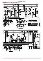
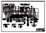
Page 51: ...C I B UNIGAS M03957CI 51 WIRING DIAGRAM Cod 05 680 Progressive burners ...
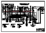
Page 52: ...C I B UNIGAS M03957CI 52 WIRING DIAGRAM Cod 05 681 Fully modulating burners ...
Page 54: ......
Page 55: ......
Page 56: ......


