is rectified by D120 and D121, thus charg
ing C160. In the absence of a carrier,
C160 will remain charged keeping the out
put of IC103 1/2 low. When a RF carrier is
present, the "rush" noise is reduced, thus
allowing C160 to discharge through R121,
causing the output of IC103 2/2 to go high.
This high is fed to the microprocessor
IC601 pin 40. The microprocessor sends
mute data to IC101 pin 9 from pin 41 of
IC601 through an inverter Q613.
Receiver Audio
The mute controlled audio signal from
IC101 pin 11 is fed to active high pass fil
ter IC102. The output of IC102 is fed to the
audio power amplifier IC105 through the
limit control, VR102, and the volume con
trol, VR751. The audio power amplifier,
IC105, amplifies the recovered audio to a
level sufficient to drive the speaker. In the
squelched mode the output of IC102 is
clamped to ground by 0107.
TX, BUSY, CALL, and DISPLAY
LEDs
The TX LED (D703) is activated by the
microprocessor pin 56 through an inverter,
0615, when the PTI closure is received
on pin 63 of IC601. The anode of D703 is
connected to the emitter of Q701, dimmer
circuit.
The BUSY LED (D705) is activated by the
microprocessor pin 55 through an inverter
0616 when a busy indication is received
on pin 40 of IC601. The anode of D705 is
connected to the emitter of 0701, the dim
mer circuit.
The
CALL LED (D702)
is activated by
the
microprocessor
pin
60
through an
inverter
0618 when a correct CTCSS tone or Two
Tone is decoded by the microprocessor.
The anode of D702 is connected to the
emitter of 0701, dimmer circuit.
The DISPLAY LED (0701) receives data
from microprocessor pin 54 which is
loaded into two shift registers, IC752 and
IC752. The clock signal for the shift
registers is provided by the IC602 pin 52.
During the time that the data is being
loaded into the shift registers the STB line
pin 53 is held low; thus, preventing the
LED from flashing with the data stream.
The anode of D701 is connected to the
emitter of Q701, the dimmer circuit.
LED Dimmer Control
When the ambient light dims, the resis
tance of the CDS cell (Y701) increases
reducing the current supplied to the base
of
0701;
thus, reducing the emitter voltage
of 0701 causing the LEDs to dim.
Microprocessor
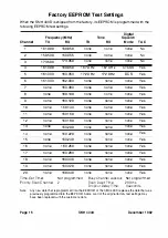
The microprocessor IC601 controls many
of the transmit and receive functions of the
transceiver. These functions include such
items as channel selection, scan, audio
muting, transmit keying, CTCSS and DCS
encode/decode. The microprocessor also
provides programming data for AMX 533
TwoTone option, if installed.
--=--
The microprocessor operates according to
the instructions that are stored in its inter
nal 4K x 8 byte ROM. This ROM is an in
tegral part of the microprocessor chip and
is maskprogrammed when the
microprocessor is manufactured. In addi
tion to the internal ROM, there is an exter
nal 256 x 8 bit E2PROM (IC603) which
stores the information
unique to the
individual radio system, such as channel
number
and frequency, DCS or CTCSS
codes,
scan,
priority channel,
busy chan
nel lockout,
and
timeout timer. The
SMU
300
is field programmable using the AMX
500C, PROM Writer.
Page 1 4
SMH
4000
December 1 992
Summary of Contents for SMH 4000
Page 20: ...Page 20 SMH 4000 December 1 992 ...
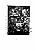
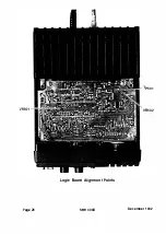
Page 24: ..._TP601 VR602 Logic Board Alignment Points Page 26 SMH 4000 December 1 992 ...
Page 26: ...Page 28 SMH 4000 December 1 992 ...
Page 27: ......
Page 47: ...CC SM 38 Revision 1 SMH 4000 December 1 992 ...
Page 49: ...SMH 4000 Exploded Mechanical View Page 1 8 S M H 4000 I 0 I 0 0 a 3 December 1 992 ...
Page 62: ... I December 1 992 SMH 4000 Earlier Version Logic PCB PD 304AC Component Side SMH 4000 Page 39 ...
Page 72: ......

