Theory of Operation
To better understand the theory of opera
tion of the
SMH
4000 refer to the block
diagram (page 17) and appropriate
schematic diagrams (beginning on
page 29).
Phase Locked Loop
The Phase Locked Loop consists of IC403
(PLL I
C
), IC402 (the prescaler),
0401
(the
active low pass filter),
IC401
(the voltage
controlled oscillator,
X401
(the reference
crystal), and a microprocessor program
ming circuit.
The PLL IC (IC403) has a programmable
reference counter, and programmable "N"
and "A" counters. The counters are
programmed serially through a common
data input (pin 10) and latched into the ap
propriate counter latch, according to the
last data bit (control bit) entered. The PLL
IC has the logic circuitry to control an exter
nal dualmodulus prescaler.
The prescaler (IC402) has a dividing ratio
of 64 or 65 which is determined by the
modulus control output from IC403, pin 12.
A 12.8 MHz crystal,
X401,
is connected to
pins 1 and 2 of the PLL
IC (IC403)
to form
the reference oscillator. This reference fre
quency is then divided by 1024, to produce
a 12.5 kHz reference frequency. This 12.5
kHz reference frequency is internally ap
plied to the phase detector section of
IC403, and to pin
13
of
IC403.
The phase
detector compares the divided VCO fre
quency to the reference frequency and is
sues an error signal which forces the VCO
frequency higher or lower until a lock condi
tion occurs.
In
the receive mode the
VCO (IC401)
oscil
lates 45.1
MHz
above the receive channel
frequency. In the transmit mode the VCO
(IC401) oscillates on the transmitting fre-
quency. The VCO frequency is shifted by
the data sent from the microprocessor
each time the PTT is pressed. The output
of the VCO (IC401) is buffered by 0205
before being fed to the prescaler (IC402)
and used as the injection frequency for the
receiver and transmitter.
The signal from the prescaler is fed to the
"A" and "N" counters
(IC403,
pin 8.) The
output of these counters is fed to the
phase detector and compared to the refer
ence signal. The phase detector output,
pins 15 and 16 of IC403, is connected to
the active lowpass filter,
0401.
The output
of 0401 controls the VCO frequency.
When the PLL is outoflock, pin 7 of
IC403
pulses low, turning 0204 OFF; this in turn,
inhibits the transmitter by turning 0202
OFF and removing the supply voltage to
0203, the TX amplifier.
The 12.800
MHz
crystal (X401) is tempera
ture compensated by a thermistor (TH401)
and a heater (0407). As the ambient
temperature drops below -51 C the resis
tance of the thermistor (TH401) increases,
causing 0405 to draw more current and
0406 to supply more current to 0407,
thereby heating the crystal and thus main
taining the frequency stability. All other
components that may have an effect on
the frequency stability have been selected
to have a minimal change with tempera
ture.
Speech Amplifier
The output of the dynamic microphone is
amplified by the speech amplifier,
0206
and
0207.
The amplified speech is then
fed to the speech limiter,
IC201 1/2, and
the active lowpass filter
IC201 2/2. This
low pass filter attenuates
the frequencies
between 3
kHz
and 20
kHz
by a factor of
Page 1 2
SMH 4000
December 1 992
Summary of Contents for SMH 4000
Page 20: ...Page 20 SMH 4000 December 1 992 ...
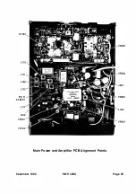
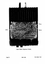
Page 24: ..._TP601 VR602 Logic Board Alignment Points Page 26 SMH 4000 December 1 992 ...
Page 26: ...Page 28 SMH 4000 December 1 992 ...
Page 27: ......
Page 47: ...CC SM 38 Revision 1 SMH 4000 December 1 992 ...
Page 49: ...SMH 4000 Exploded Mechanical View Page 1 8 S M H 4000 I 0 I 0 0 a 3 December 1 992 ...
Page 62: ... I December 1 992 SMH 4000 Earlier Version Logic PCB PD 304AC Component Side SMH 4000 Page 39 ...
Page 72: ......


