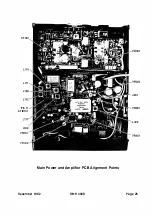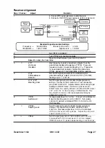
Alignment P rocedures
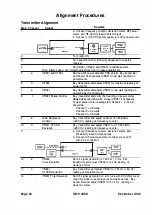
Transmitter Alignment
Step Channel
Adjust
Remarks
1
2
3
4
5
2
6
3
7
2
8
1
9
2
1 0
3
1 1
1 2
2
1 3
4
1 4
Page 24
•13.6 voe
Power Slipply
Power COf'Vl8ctor
SMU 300
a. Connect frequency counter, deviation meter, RF power
meter, and RF dummy load to antenna jack.
b. Connect
+
1 3.6 VDC power supply to radio's power cord.
Antenna
RF Power
Meter
Turn radio ON.
500
RF
D.mvny
Load
Frequency
Co1.M1ter
Deviation
Meter
Turn squelch control (SQ) fully clockwise to squelch
receiver
Set VR201 , VR202, and VR601 to middle position.
Note: Always use a non-metallic adjustment tool to make adjustments.
VR301 and CT301
Remove RF power amplifier PCB shield. Key transmitter
and Power Control adjust VR301 for 42 watt reading on
power meter.
CT301
Key transmitter and adjust CT301 for maximum reading on
power meter.
VR301
Key transmitter and adjust VR301 for 42 watt reading on
power Power Control meter.
VR301 Power Control
L402 Reference
Ocillator
VR401 CTCSS
Deviation
AF SiO'lal
Generator
VR202
Voice Deviation
VR601
CTCSS Deviation
VR201 Total Deviation
Key transmitter and verify that reading on power meter
does not
exceed 50 watts. Adjust VR301 if necessary.
Typical power meter readings for channels 1 , 2, and 3
should be:
Channel 1
=
48 watts
Channel 2
=
42 watts
Channel 3
=
38 watts
Key transmitter and adjust L402 for 1 50.505 M Hz
(±200 Hz) reading on frequency counter.
Key transmitter and adjust VR401 for 1 73 .500 MHz
(±200 Hz) reading on frequency counter.
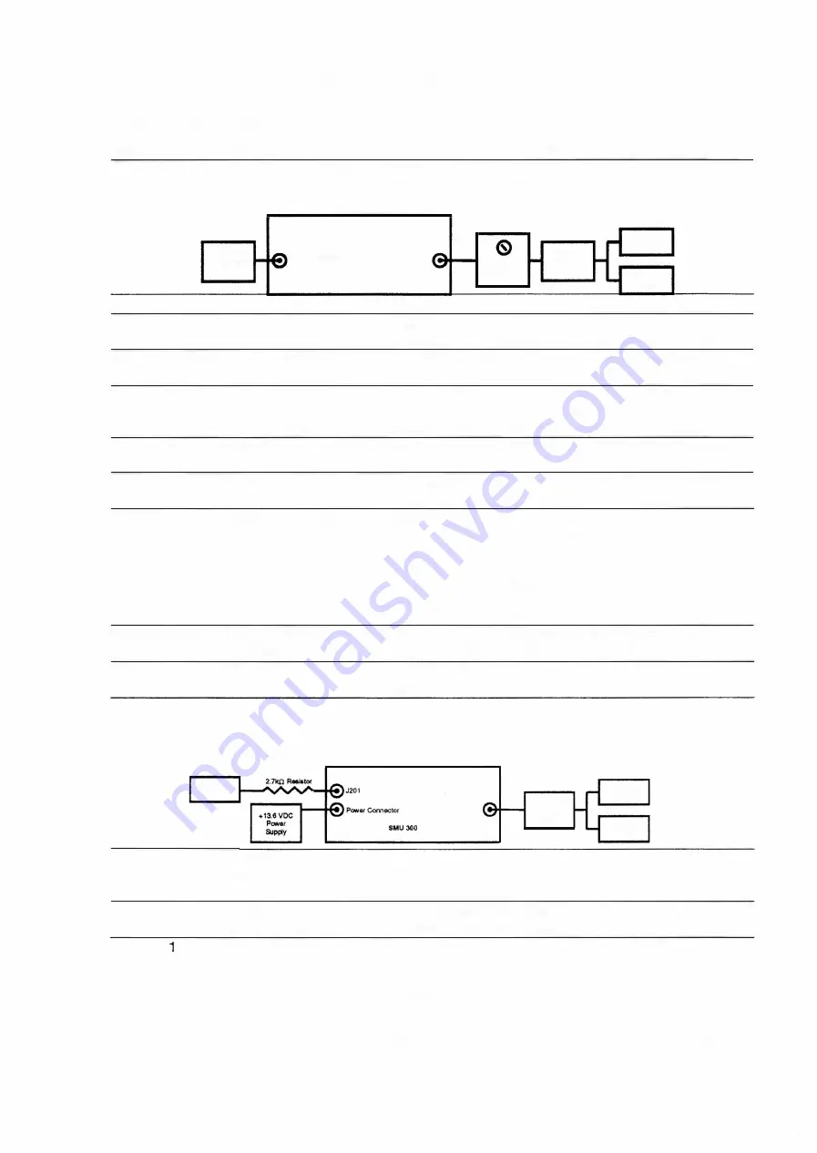
a. Connect frequency counter, deviation meter, and
RF dummy load to antenna jack.
b. Connect AF signal generator to either pin of J201
with 2.7 k n resistor.
Antenna
5(0 RF
Dummy
Load
Frequeney
Counter
Ooviation
Meter
Set AF signal generator to 1 kHz at 1 Vrms. Key
transmitter and adjust VR202 for 2 kHz reading on
deviation meter.
Key transmitter and adjust VR601 for 750 Hz (± 50 Hz)
reading on deviation meter.
Set AF signal generator to 1 kHz tone with 30 mVrms level.
I nput this signal to audio input of microphone jack. Key
transmitter and adjust VR201 for 4.7 k Hz reading on
deviation meter.
SMH 4000
December 1 992
Summary of Contents for SMH 4000
Page 20: ...Page 20 SMH 4000 December 1 992 ...
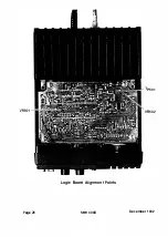
Page 24: ..._TP601 VR602 Logic Board Alignment Points Page 26 SMH 4000 December 1 992 ...
Page 26: ...Page 28 SMH 4000 December 1 992 ...
Page 27: ......
Page 47: ...CC SM 38 Revision 1 SMH 4000 December 1 992 ...
Page 49: ...SMH 4000 Exploded Mechanical View Page 1 8 S M H 4000 I 0 I 0 0 a 3 December 1 992 ...
Page 62: ... I December 1 992 SMH 4000 Earlier Version Logic PCB PD 304AC Component Side SMH 4000 Page 39 ...
Page 72: ......

