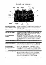
TX LED,
CALL LED
BUSY
LED
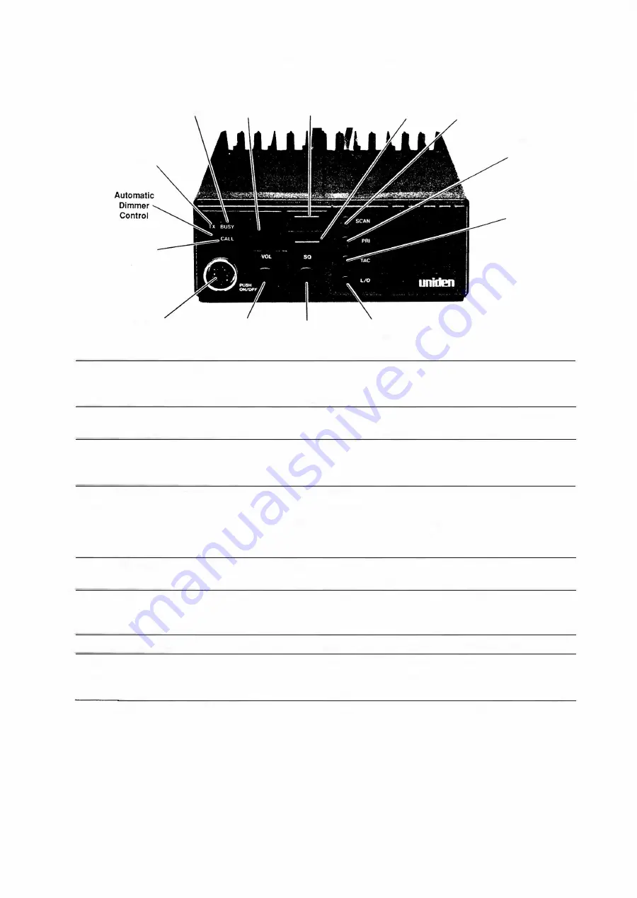
Controls and Indicators
Channel
Display
Channel Up
Switch
Channel
Down
Switch
SCAN
Switch
PRI
Switch
TAC
·switch
Microphone
Jack
VOL
and
PUSH
ON/OFF
Control
SQ
Control
LIO
Switch
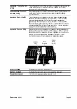
On/Off Volume Control
Press this control to switch the radio's power on or off. Rotate this
(PUSH ON/OFF and VOL)
control clockwise to i ncrease the volume or counterclockwise to
decrease the volume.
M icrophone Jack
DIN 5-pin conn ector. Use only supplied mi crophone or approved
option for optimum commun ications.
Call Indicator (CALL)
This yellow LED lights and remains on when your radio receives a
frequency with the proper CTCSS tone or DCS code. Press the
PTT switch to turn off the Call LED.
Automatic Dimmer
Control
Transmit Indicator (TX)
Busy Indicator (BUSY)
Channel Display
Channel Up/Chan nel
Down Switches
Scanner Switch (SCAN)
Pag
e
8
This control adjusts the intensity of the radio's indicators. If tl1e
am bient light level increases, the intensity of the radio's indicators
increases. If the ambient light l evel decreases, the i ntensity of the
radio's indicators decreases. This control calls for no operator
adjustments.
This red indicator l ights when you press the PPT switch and
shows that the radio is transmitting.
This yellow indicator lights if a carrier is present on the receive
channel. This shows transmit activity on the channel by another
radio.
This green LED display shows the current channel number.
Press the Channel Up Switch to increment the channel number
shown in the Channel Display. Press the Channel Down Switch to
decrement the channel number shown in the Channel Display.
Press this switch to turn the scan feature on or off. Leave the scan
feature on if you want to monitor the transmit activi
ty
of other
radios. When you remove the m icrophone hang-up button from
ground, the scan feature pauses. When you ground the
microphone hang-up button, the scan feature resumes.
SMH
400D
December
1 992
Summary of Contents for SMH 4000
Page 20: ...Page 20 SMH 4000 December 1 992 ...
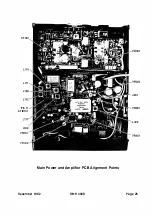
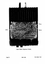
Page 24: ..._TP601 VR602 Logic Board Alignment Points Page 26 SMH 4000 December 1 992 ...
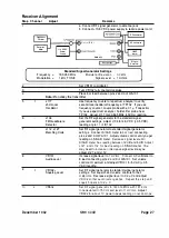
Page 26: ...Page 28 SMH 4000 December 1 992 ...
Page 27: ......
Page 47: ...CC SM 38 Revision 1 SMH 4000 December 1 992 ...
Page 49: ...SMH 4000 Exploded Mechanical View Page 1 8 S M H 4000 I 0 I 0 0 a 3 December 1 992 ...
Page 62: ... I December 1 992 SMH 4000 Earlier Version Logic PCB PD 304AC Component Side SMH 4000 Page 39 ...
Page 72: ......


