background image

a) Mounting points

All compressors should be mounted firmly and securely to the engine bracket using 

manufacturers’ standard specifications. The following chart outlines the minimum mounting 

point utilisation for each Unicla model.
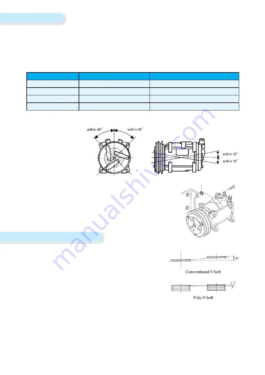
b) Mounting angle

The mounting angle 

for each model must 

be as follows:

c) Lug type mounting

When mounting Unicla UP series compressors (lug mount type) 

there must be no gap between the bracket and the lug. This will 

ensure additional stress is not placed on the compressor and noise 

transmission is kept to a minimum. Universal sliding bushes or shims, 

or Unicla shim kit part no 2900-000010 must be used as follows:

4. Belt alignment and tension

a) Alignment

The compressor clutch pulley must be in perfect alignment 

with the drive pulley on the engine and any auxiliary idler or 

adjusting system. Unacceptable alignment is shown in the 

following diagram

b) Tension

Belt tension adjustment should be made so the belt is taut, but not to excess to cause excessive 

bearing loads. Due to the pulsating load created by compressors, the belt tension must be 

greater than for a normal steady load. The tension must be within the manufacturers’ guidelines 

for the specific belt used to drive the compressor, or in the absence of this information, Unicla 

recommends belt deflection of 10 - 20 mm /meter after tensioning, or 50kg of tension for most 

applications. This tension must be checked again and tighten back to specification after 36-48 

hours of initial operation.

3.  Mounting

3.

Compressor type

Mounting description

Minimum mounting requirement

UC

Alternator or swing type

Three lugs

UP

Lug type

Four lugs

UX

Direct or bolt through type

Four points

UWX

Multiple direct mounting

Six points

Summary of Contents for 90 Series

Page 1: ...Compressor Fitting Guidelines for New Applications...

Page 2: ...ining professional information using representative graphs charts and tables Manufacturers specifications must be consulted for specific guidelines and performance data Unicla published data specific...

Page 3: ...selection 6 9 Recommended suction line pipe size 7 8 10 System validation 9 10 11 Other features performance information 11 Note This booklet is designed to assist the installing technician to ensure...

Page 4: ...for 4 5 revolutions to ensure proper lubrication to the working assembly components This will avoid damage during initial start up c Service manual If any disassembly of compressor components is requ...

Page 5: ...drive pulley on the engine and any auxiliary idler or adjusting system Unacceptable alignment is shown in the following diagram b Tension Belt tension adjustment should be made so the belt is taut but...

Page 6: ...e clutch design varies depending on direction of rotation Later generation rubber clutches are designed to operate in both directions making the compressor and clutch assembly multi directional Failur...

Page 7: ...be identical to the native oil already installed to the specific Unicla compressor as identified on the compressor label d Oil separators Oil separators are strongly recommended in multiple evaporato...

Page 8: ...e you have selected the Refrigerating Capacity Graph A complete range of graphs for each model is available from Unicla upon request For single evaporator applications the compressor must cater for th...

Page 9: ...6 16 5 8 0 98 10 16 5 8 0 43 4 5 19 3 4 0 65 6 7 19 3 4 1500 3 6 0 59 6 16 5 8 0 43 4 5 19 3 4 0 72 7 4 19 3 4 0 87 8 9 19 3 4 0 61 6 2 22 7 8 2000 4 9 0 95 9 7 16 5 8 0 70 7 2 19 3 4 0 54 5 6 22 7 8...

Page 10: ...3 8 0 99 10 1 35 1 3 8 2500 26 7 0 64 6 5 28 1 1 8 0 44 4 5 35 1 3 8 0 74 7 6 35 1 3 8 0 89 9 1 35 1 3 8 0 56 5 7 41 1 5 8 3 m Pipe Length 6 m Pipe Length 10 m Pipe Length 12 m Pipe Length 18 m Pipe L...

Page 11: ...rated due to inadequate cooling vapour return to the compressor or excessive external thermal loads on the suction line and or the compressor It is important that all Unicla compressors are operated w...

Page 12: ...educed giving less cooling medium excessive low side superheating means the suction vapours are no longer cold The result is not only a low quantity of cooling vapours but they are no longer cold 10 N...

Page 13: ...quate flow of refrigerant back to the compressor and valuable cooling is not given to the compressor under high heat load conditions This can be diagnosed by determining if a pressure drop is evident...

Page 14: ...la International Limited Unit 1209 1210 12F Manhattan Centre 8 Kwai Cheong Rd Kwai Chung N T Hong Kong Phone 852 2422 0180 Fax 852 2422 0680 Email sales unicla hk Website www unicla hk Unicla Cat No B...

Reviews: