


Touch Screen
30
4.9
DIAGNOSTIC ERRORS
4.9.1
ACTIVE ALARMS
You can display the current alarms of the connected units. To do this, from the home page, press the triangle icon of danger, if
present; from here you can access to the list of all active alarms in the system.
Also, when you are in an unit page (i.e. Chiller page, see Paragraph 3.4.1), by pressing the triangle that appears on the machine, you
go to a menu where you can see current alarms of the selected machine.
4.9.2
ALARM HISTORY
The keyboard manages a detected alarms list for all the plant that shows the date and time of the alarm, the affected machine and
alarm type. In the historic are stored up to 100 alarms, once exceeded the limit, it automatically deletes the older alarms.
To go to the alarm history: from the system main page, go into "
Configuration
" -> "
Service menu
" -> "
Alarm list
".
Having maintainer password, you can set that the alarm history is also accessible from the user menu; to do this go into
"C
onfiguration
" -> "
Service menu
" -> "
Parameters
" -> "K
eyboar
d" ->
Par 33/65: Enable user alarm log = 1
.
4.10
DOUBLE SET-POINT FUNCTION
The double set-point function introduces a second plant side set-point (both in cooling mode and in heating mode).
The application field is primarily that of the floor-cooling assisted by fancoil units for dehumidification.
The purpose of the application is to prevent in any condition the formation of condensation on the floor, and in any case to ensure
the welfare thermo hygrometric.
The activation of the double set-point is by means of maintainer parameters (from System main page ->
Configuration
->
Service
menu
->
Parameters
->
Chiller
->
Chiller name
->
H129: Enable second setpoint
≥ 2
, ref. the control manuals of the chiller unit for
allowable values). It is required also to set a digital output for controlling the three-way valve used to divert the flow of water
between the floor and fan coils. The function of humidistat is instead carried out directly by the Touch Screen remote control panel,
by means of its integrated sensors and the logic internally implemented related to the control of dew point and dehumidification.
Please refer to the manual of the chiller for the correct setting of parameters related to the double set-point, as well as for the
electrical connections to be done in the terminal board of the chiller.
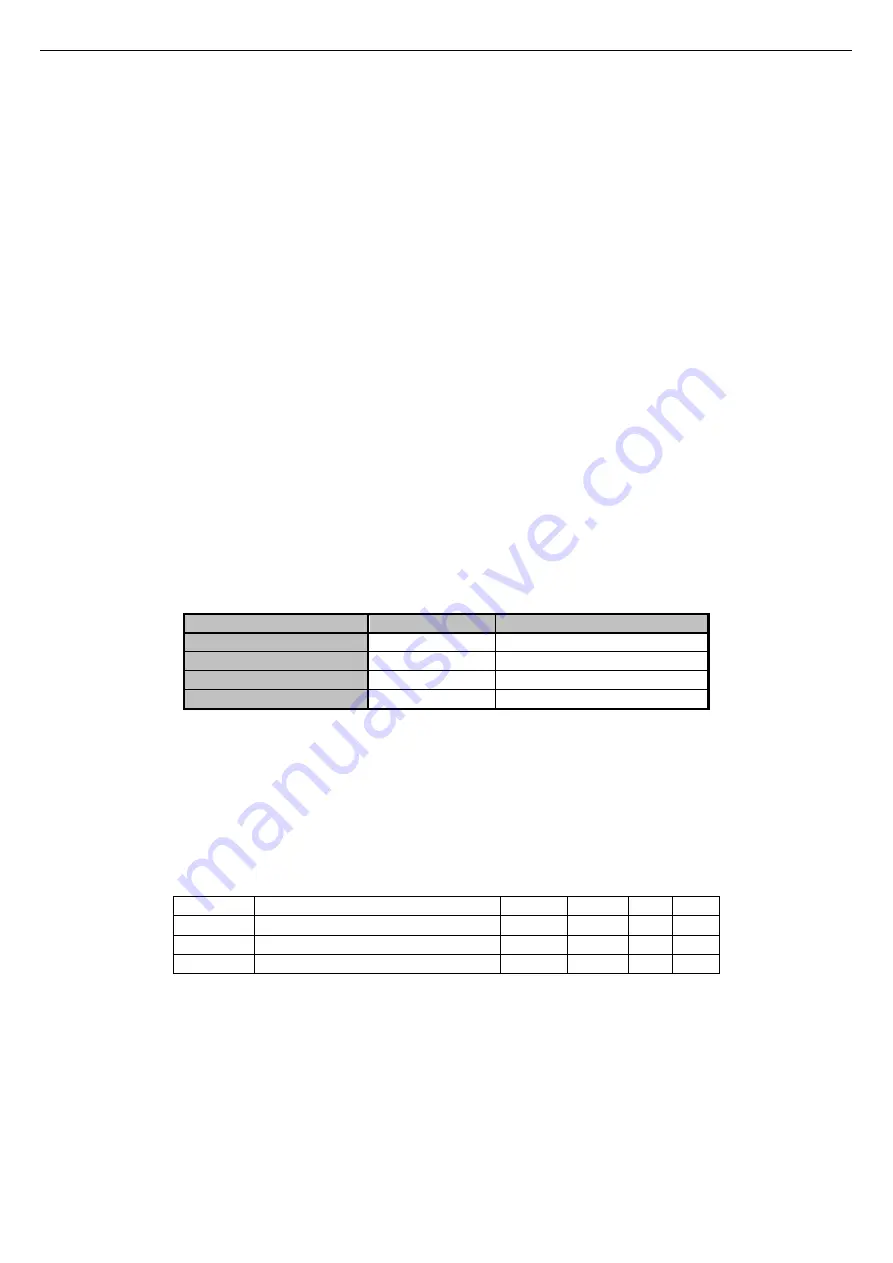
The set-points can be set with double set-point function enabled are:
Setpoint
Setpoint on Touch
Setpoint onboard control panel
First setpoint (°C)
T water
Coo/Hea
First setpoint eco (°C)
T Water ECO
Second setpoint (°C)
T2 water
Co2/He2
Second setpoint eco (°C)
T2 water ECO
Table 4. Set point settings with enable double set point.
To manage the setpoint:
•
from the Touch Screen controller
→
“
Set-point setup
” menu -> “
Chiller
” ->”
Summer
” o “
Winter
” (see Paragraph 4.7.3).
•
from the on-
bard control panel →
SET button.
The second setpoint is greater than the first set point in summer and lower in winter:
•
in summer: T
2
≥
T
•
in winter: T
2
≤
T
The parameters to be set for the management of dehumidification are accessible from the service menu (
Configuration
->
Service
menu
->
Parameters
-> K
eyboard
):
Parameter Name
Unit
Default Min. Max.
Par 42/65 Dew-point temp. margin
°C
5.0
0.0 50.0
Par 43/65 Min. staying time in dehumidification Seconds
300
0
600
Par 44/65 Max. staying time in dehumidification Seconds
600
0
1200
Table 5. Service keyboard parameters for dehumidification
Note 1: Set the lower limit of the winter first setpoint to 25°C
•
set the parameter
H129 to be
3 or 4.
•
Set the Winter second setpoint from 35°C to 25°C
•
Re-set the parameter
H129
to be 0
•
Now it’s possible to decrease the winter setpoint to 25°C.
Note 2:
If in the chiller is configured the presence of a digital input to the management of the second set point (chiller parameter
H53=26,
terminals SE-SE, ref. Chiller manual), the management of the humidity control is not done from the remote control.
The digital input is also possibly used for switch between the first and second set point during operation in winter mode.
Summary of Contents for TOUCH SCREEN N
Page 1: ...USER S AND INSTALLER S MANUAL LCD Touch Screen Centralized Remote Controller TOUCH SCREEN_N...
Page 42: ......
Page 43: ......


