background image


 Touch Screen 

26 


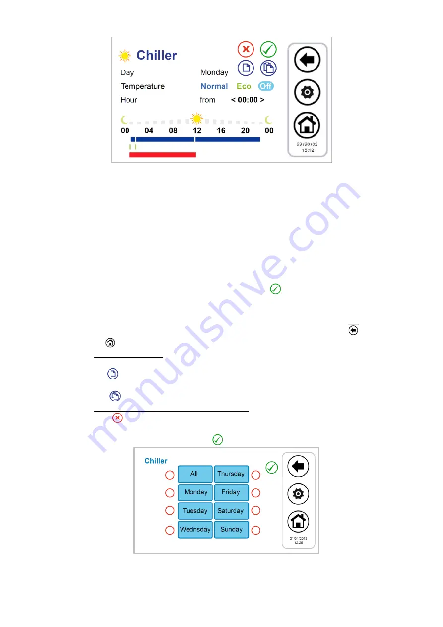
Figure 24. Chronothermostat, "Summer Chiller" page 


1.


Scheduling of a day time-line: 


press on the day currently displayed to move to the next days and select a day;  


choose if you want to set the way of operation in normal mode (press "

Normal

"), or Economy (press 

"Eco

"), or if you want 

to set to Off (press "

Off

"); 


check that after "

Hour

" appears the word "

From

" (if appears instead the word "

To

", you need to press it once to display the 

word "

From

") and select the hour and minute (the minimum allowable variation is 15 minutes)for the beginning of the time 

period;


press once on the 

"From

" in a manner that appears the word "

To

" and select the hour and minute (the minimum variation 

permitted is 15 minutes) for the end of the time period;


confirm the single time period pressing the green symbol of confirmation 


afterwards you can observe that, correspondingly to the selected time period, you will see a time-line bar of the colour of 

the type of the selected set (if normal blue, green when in economy mode, no bar in "Off"); 


repeat the above steps for all the time slots that you want to set on that particular day. 


To exit and save changes you have made (on the whole program, for all week), press the <ESC> 

 button, while if you 

press the <Home> 

 button, you will exit without saving the changes. 

2.


It is possible to copy the programming for a particular day in another day; to do this: 


select the day you want to copy the scheduling; 


press the copy icon 


select the day on which you want to copy the scheduling; 


press the paste icon 

3.


It is possible to erase the programming of certain day or of all days, to do this: 


press the delete icon 


at this point a screen will appear where you can select individual days to delete or select all the days; 


to confirm your selections, press the confirmation tick 

 on the top right side. 


Figure 25. Chronothermostat, erase programming page 


Summary of Contents for TOUCH SCREEN N

Page 1: ...USER S AND INSTALLER S MANUAL LCD Touch Screen Centralized Remote Controller TOUCH SCREEN_N...

Page 2: ...4 SPECIAL FUNCTIONS PAGE 17 3 6 5 CONFIGURATION PAGE 17 3 6 6 HELP PAGE 19 4 MACHINES STATUS AND FUNCTIONS 20 4 1 NEWTORK MANAGEMENT 20 4 2 REMOTE CONTROL CONNECTION WITH MULTIPLE CHILLERS IN THE NETW...

Page 3: ...4 12 SECONDARY CIRCULATOR 33 4 13 OTHER FUNCTIONS 33 4 14 SPECIAL FUNCTIONS 33 4 14 1 SCREED FUNCTION 33 4 15 PASSWORD AND PROTECTIONS 34 5 REMOTE ACCESS 34 5 1 SECURITY 34 5 2 LOCAL WEB SERVER 34 6...

Page 4: ...ts and parameters of the first circuit can be displayed 1 2 USE NOT PERMITTED Any use different than that permitted is PROHIBITED 1 3 TECHNICAL DATA Features Nominal Min Max Power supply voltage 12Vac...

Page 5: ...the screens Do not put the touch screen in contact with other electrical devices Electrostatic discharge may cause a malfunction 2 1 3 DISPLAY The display is a TFT LCD 16 9 format with a diagonal 4 3...

Page 6: ...1 GNDR Ground touch screen RS 485 Modbus RTU GNDR Comunicazione Modbus X 5 1 R Modbus RTU touch screen signal R X 5 2 R Modbus RTU touch screen signal R 2 4 INSTALLATION The Touch Screen control is u...

Page 7: ...e The colour saturation indicates that icon is usable when pressed the related function is performed The transparency de saturated indicates that icon is not usable and any touch on it has no resultin...

Page 8: ...ss to information on the firmware version 6 Configuring the Ethernet network 7 Log out intermittent symbol if it s active 8 Arrow of navigation next page Graphically it also contains information on th...

Page 9: ...ctly the following information referreing to fancoil units Presence of fancoil unis that are connected to the network if the fancoil symbol appears on the display Figure 8 Fancoil units connected to t...

Page 10: ...5 Chiller heat pump with working signalling function given by the rotation of the fans from here you access to an additional page of information about that specific chiller 6 Active alarms of the disp...

Page 11: ...r temperature C Outlet water temperature C Sanitary probe temperature if it s present and configured C Accessing the same page with service or manufacturer access right to enable the access right pres...

Page 12: ...TARY INTEGRATION RESISTANCE 3 PLANT INTEGRATION RESISTANCE 4 BOILER ENABLEMENT 5 DOUBLE SET POINT 6 DEHUMIDIFYING 7 SLAB FEATURE 8 DEFROST 9 ANTIFREEZE WATER 10 ANTIFREEZE TRAY RESISTANCE Table 1 Orde...

Page 13: ...the next fancoil unit on the network 3 the name of the zone to which the fancoil belongs and the fancoil identification number are reported every time you press the name area you switch to the next fa...

Page 14: ...onfigured function but note active Herein below is reported a table with icons that may appear in the scrollable sidebar The presence absence of the icon in the sidebar depends on the status of its co...

Page 15: ...the system The field 3 indicates the chiller which it refers by pressing on it you progress to the next chiller in the network For each chiller shown you see the readings on the temperature of the wa...

Page 16: ...STATUS SETUP 2 SET POINT SETUP 3 PROGRAMS AND CHRONO THERMOSTAT In the bottom from the left to right 4 SPECIAL FUNCTIONS 5 CONFIGURATION 6 HELP MENU 3 6 1 STATUS SETUP PAGE Press the button to enter...

Page 17: ...age From this page you can set separately the weekly program of each chiller and zones of fancoils You can also program the legionella s cycle and the production of hot water if enabled see Paragraph...

Page 18: ...e pages of the parameters until you find the desired parameter press on the currently set value the present value turns red to indicate that it can be changed by using the up and down arrows Select th...

Page 19: ...ess the confirmation tick Note If you press outside the confirmation area it returns again the previously value 3 6 5 3 MANUFACTURER MENU To access to the manufacturer menu you must set the manufactur...

Page 20: ...connect the chiller and the remote control Touch Screen as shown in the drawing In the remote control Touch Screen by setting the parameter Par 8 65 Configuration Service Menu Keyboard related to the...

Page 21: ...the installation and utilization of the remote control panel for water terminal units management it is recommended to separately power on the water terminal units fancoils each terminal unit must be i...

Page 22: ...n is not totally configurable by Touch Screen controller It is necessary to act directly on the chiller heat pump on board controller only if present expansion module by setting the parameters H85 to...

Page 23: ...or the settings related to the function please refer to paragraph AMBIENT THERMOSTAT Note Once the status is set from the Touch Screen control panel you must wait a minute to ensure that communication...

Page 24: ...SET POINT Management procedure of the set point of the different zones and chillers 1 from the system main page go to Set point setup 2 at this point you find a list of assigned chillers and the areas...

Page 25: ...e zones in winter mode In addition if is enabled the sanitary mode from System main page Configuration Service menu Parameters Chiller Chiller name H10 sanitary presence 1 you can access to two other...

Page 26: ...rve that correspondingly to the selected time period you will see a time line bar of the colour of the type of the selected set if normal blue green when in economy mode no bar in Off repeat the above...

Page 27: ...is respectively Summer sanitary Winter sanitary Only sanitary 4 7 4 3 ZONES AND FANCOILS WEEKLY PROGRAM In a similar way to the scheduling of the chillers it is possible to set the weekly program of e...

Page 28: ...NT THERMOSTAT The Touch Screen control panel can operate as a typical ambient thermostat The ambient thermostat function for each zone will be enabled disabled using the corresponding button at the bo...

Page 29: ...SETTINGS PROCEDURE 4 8 1 SETTING OF LANGUAGE AND DATE TIME To set the keyboard language 1 from the system main page go to Configuration 2 then go to User menu 3 enter the user password and press the...

Page 30: ...ion of humidistat is instead carried out directly by the Touch Screen remote control panel by means of its integrated sensors and the logic internally implemented related to the control of dew point a...

Page 31: ...for the calculation of the dew point is the Magnus Tetens approximation this approximation is valid for values of Td between 0 C and 50 C therefore if the calculation gives a value out of these limit...

Page 32: ...o avoid returning immediately in this case it requires a minimum staying in adjustment to the radiant panels still given by Par43 65 Max staying time in dehumidification 4 11 CLIMATIC COMPENSATION It...

Page 33: ...oiler integration defrosting cycle water side or air side anti freeze heaters etc please refer to chillers and fancoils instructions manuals 4 14 SPECIAL FUNCTIONS From the main menu choosing the icon...

Page 34: ...unlock the screensaver set by default to 0 and modifiable by accessing to user s parameters see Paragraph 3 6 5 1 5 REMOTE ACCESS The device can interact with the local network by an Ethernet port acc...

Page 35: ...o shift to next available pages click on the links at the page bottom Figure 38 Touch Screen Ethernet Command page The commands present in the Command page are referred to the entire system The operat...

Page 36: ...t points set for the winter season water set point economy water set point and if enabled double set point second water set point and second water economy set point appear under Winter while under the...

Page 37: ...oard USB port For the upgrade copy the upgrade file in the main root of a USB pen drive insert the pen drive into the Touch Screen USB port enter into Configurations User s menu see Paragraph 3 6 5 1...

Page 38: ...C Heat 20 0 35 0 15 0 C 19 m5 comp Text FC 10 0 10 0 0 0 20 m6 comp Text FC 10 0 10 0 0 0 21 Set2 Text comp CHIL Cool 0 0 50 0 20 0 C 22 Set2 Text comp CHIL Heat 20 0 35 0 10 0 C 23 Second m1 comp Tex...

Page 39: ...um temp of the fancoils of the zone 2 Maximum temp of the fancoils of the zone 3 Temperature measured by the Touch Screen control panel 0 3 1 50 Regulation temperature in zone 5 Winter 0 Average temp...

Page 40: ...imum temp of the fancoils of the zone 2 Maximum temp of the fancoils of the zone 3 Temperature measured by the Touch Screen control panel 0 3 1 58 Regulation temperature in zone 4 Summer 0 Average tem...

Page 41: ...2 Maximum temp of the fancoils of the zone 3 Temperature measured by the Touch Screen control panel 0 3 1 63 Regulation temperature in zone 9 Summer 0 Average temp of the fancoils of the zone 1 Minim...

Page 42: ......

Page 43: ......

Page 44: ...printing errors It also reserves the right to modify its products as deemed necessary or useful without jeopardising their essential features 46033 casteldario mantova italia tel 39 0376 57001 fax 39...

Reviews: