background image

General Safety Overview

This instrument strictly complies with the safety requirements for electronic measuring instrument IEC 61010-1 safety 
standard during design and manufacturing. Please understand the following safety preventative measures, to avoid 
personal injury, and to prevent damage to the product or any connected products. To avoid possible dangers, be sure 
to use this product in accordance with the regulations.  
 

Only trained personnels can perform the maintenance program.

Avoid fire and personal injury.

Use the correct power line: 

Only use the dedicated UNI-T power supply appointed to the local region or country for this product.

Correct Plug: 

Don't plug when the probe or test wire is connected to the voltage source.

Ground the product: 

This product is grounded through the power supply ground wire. To avoid electric shock, grounding conductors must be 
connected to the ground. Please be sure that the product is properly grounded before connecting to the input or output of 
the product.

Correct connection of oscilloscope probe: 

Ensure that the probe ground and ground potential are correctly connected. Do not connect ground wire to high voltage.

Check all terminal ratings: 

To avoid fire and the large current charge, please check all the ratings and the marks on the product. 
Please also refer to the product manual for details on the ratings before connecting to the product.

Do not open the case cover or front panel during operation

Only use fuses with ratings listed in the technical index 

Avoid circuit exposure: 

Do not touch exposed connectors and components after power is connected.

Do not operate the product if you suspect it is faulty, and please contact UNI-T authorized service personnel for inspection. 
Any maintenance, adjustment, or replacement of parts must be performed by UNI-T authorized maintenance personnels.

Maintain proper ventilation

Please do not operate the product in humid conditions

Please do not operate in inflammable and explosive environment

Please keep the product surface clean and dry

Safety Terms and Symbols

The following terms may appear in this manual:

Warning: 

The conditions and behaviors may endanger life.

Note: 

The conditions and behaviors may cause damage to the product and other properties.

          The following terms may appear on the product:

Danger: 

Performing this operation may cause immediate damage to the operator.

Warning: 

This operation may cause potential damage to the operator.

Note: 

This operation may cause damage to the product and devices connected to the product.

The following symbols may appear on the product:
 

3

Summary of Contents for UPO2000E Series

Page 1: ...UPO2000E Series Ultra Phosphor Oscilloscope User Manual...

Page 2: ...customer refers to the individual or entity that is declared in the guarantee In order to obtain the warranty service customer must inform the defects within the applicable warranty period to UNI T an...

Page 3: ...o avoid fire and the large current charge please check all the ratings and the marks on the product Please also refer to the product manual for details on the ratings before connecting to the product...

Page 4: ...ings Chapter 6 Protocol Decoding Chapter 7 Mathematical Operations Chapter 8 Display System Settings Chapter 9 Automatic Measurements Chapter 10 Cursor Measurements Chapter 11 Storage and callback Cha...

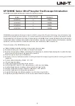
Page 5: ...ate of up to 1GS s can observe faster signals Maximum storage depth of 56Mpts which allows the oscilloscopes to maintain a high sampling rate in a wider time base taking into account the structure and...

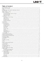
Page 6: ...op 12 6 Single Trigger 12 7 Clear 12 8 Print Screen 13 9 Multipurpose knob 13 10 Function Keys 13 1 6 User Interface 14 1 7 Special Symbols Introduction 15 Chapter 2 Vertical Channel Settings 15 2 1 O...

Page 7: ...3 Application of XY Mode 46 Chapter 9 Automatic Measurement 47 9 1 Parameter Measurement 47 9 2 Automatic Measurement Menu 48 9 3 All Parameters Measurement 49 9 4 User Defined Parameters 49 Chapter...

Page 8: ...al operations please follow the steps below 1 Connect to the Power Supply The power supply voltage range is from 100 VAC to 240 VAC the frequency range is 45Hz to 440Hz Connect the oscilloscope to the...

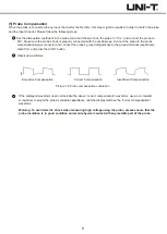
Page 9: ...e probe s ground alligator clip to the ground terminal respectively Open CH1 and press the AUTO button Observed waveforms Excessive Compensation Correct Compensation Insufficient Compensation Picture...

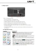
Page 10: ...stop Single trigger control All clear Probe compensation signal connector and ground terminal Trigger control area Horizontal control area Analog channel inputs Vertical control area Control menu USB...

Page 11: ...key to open the related channel menu or activate and close the channel MATH Press this key to open the mathematical operation menu for add subtract multiply divide FFT logic and advanced operations RE...

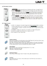
Page 12: ...e trigger level value at the top right of screen will change in real time Press the knob to quickly return the trigger level to the 50 of trigger signal 2 TRIG MENU Displays the trigger menu For detai...

Page 13: ...ose knob and the measurement result will appear at the bottom of the screen ACQUIRE Sampling setting menu for setting the acquisition mode and deep storage CURSOR Cursor measurement menu users can mea...

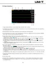
Page 14: ...igger Level Indicates the current trigger level value corresponding to the on the right side of the screen can be adjusted with the trigger level knob 6 CH1 Vertical Identification Displays CH1 activa...

Page 15: ...e No waveform displays on the corresponding channel For any opened and activated channel pressing its channel button can close that channel c Activated Only one channel in opened state will be activat...

Page 16: ...m voltage value will be reversed and the icon will appear in the vertical bar Picture 2 1 RP Closed Picture 2 2 RP Open 2 7 Bias When the DC component amplitude in the signal is relatively large wavef...

Page 17: ...time base the waveform will expand or compress according to the trigger point position 3 2 ROLL mode When the trigger mode is auto adjust SCALE knob in the horizontal control area to change the horizo...

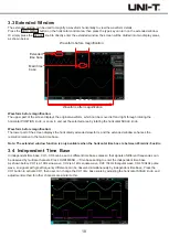
Page 18: ...extended window enhances the resolution relative to the main time base Note The extended window function is only available when the horizontal time base is between 20ms div 5us div 3 4 Independent Ti...

Page 19: ...ow Chapter 4 Sampling System Settings Sampling is taking analog input signal and converts it into discrete points by using the analog to digital converter ADC Press the ACQUIRE key to enter the sample...

Page 20: ...ory depth UPO2000E oscilloscopes displays the sampling rate in real time at the top status bar user can change the horizontal time base by adjusting the horizontal SCALE knob or change the memory dept...

Page 21: ...his mode 3 High Resolution In this acquisition mode the oscilloscope averages the neighboring points of the sampled waveform which can reduce random noise from the input signal and generate smoother w...

Page 22: ...front panel as a trigger signal External Trigger Select the EXT Trig EXT or EXT 5 input terminal input signal from the oscilloscope rear panel as a trigger signal For example the external clock input...

Page 23: ...alyzing the pre trigger data it can help to find out the cause of the burr 6 Forced Trigger Press the FORCE key to generate a forced trigger signal If the waveform is not displayed in normal or single...

Page 24: ...CH1 and the trigger level is 0 00V The Pulse Width Trigger Menu Source Press the source button to select any of CH1 CH2 CH3 CH4 AC Line EXT and EXT 5 Thr selected source will be displayed on the uppe...

Page 25: ...ield is in the rear 3 SECAM The frame frequency is 25 frames per second the TV scan line is 625 lines interlaced scanning Video Synchronization Press the video synchronization button to select the eve...

Page 26: ...he set slew rate 2 Triggers when the slew rate of the trigger signal is less than the set slew rate 3 Triggers when the slew rate of the trigger signal is basically the same as the set slew rate Time...

Page 27: ...ght corner of the screen Note Only selecting the channel with connected signals as a trigger source can obtain a stable trigger Polarity Press the polarity button to select the trigger polarity of pos...

Page 28: ...ltage level is lower than the set low level 3 Any edge Triggers on any edge of the input signal and when the voltage level meets the set level Trigger Setting Please refer to the Trigger Setting in th...

Page 29: ...of source 2 2 Falling edge Set to trigger at the falling edge of source 2 Condition Press PgDn condition to select 1 Triggers when the time difference T between the edge set by source 1 and the edge s...

Page 30: ...n select the rising edge falling edge and any edge The currently edge type is displayed at the upper right corner of the screen 1 Rising edge Set to start timing when the rising edge of the input sign...

Page 31: ...e trigger level of the channel 2 L Set the code value of the selected channel to Low that is the voltage level is lower than the trigger level of the channel 3 X Set the code value of the selected cha...

Page 32: ...CH1 CH2 CH3 or CH4 Note Only selecting the channel with connected signals as a trigger source can obtain a stable trigger Code Press the code key to select H or L 1 H Set the valid code of the data s...

Page 33: ...ource is CH1 it is triggered at the rising edge and the trigger level is 0 00V Nth Edge Trigger Menu Source Press the source button to select any of CH1 CH2 CH3 or CH4 The currently selected source is...

Page 34: ...r source is CH1 and the trigger level is 0 00V N Edge Trigger Menu Source Press the source button to select any of CH1 CH2 CH3 or CH4 The currently selected source is displayed at the upper right corn...

Page 35: ...es which can be chosen between 5 to 8 data bits there may be no parity bits or the odd parity or even parity can be selected and the stop bit can be 1 bit or 2 bits In the following instruction a data...

Page 36: ...et it to 1 bit or 2 bits Parity Press PgDn parity to set the parity mode for data transmission you can choose none even parity or odd parity Trigger Condition Press PgDn trigger condition to select st...

Page 37: ...compatible and can be combined Both SCL and SDA are connected to power through pull up resistors When the bus is vacant the two lines are at high level When any component of bus outputs low level the...

Page 38: ...nd the data relationship meets the set conditions during the transmission process This trigger condition makes it easy to implement the I2C s specified address and data trigger and help to analyze the...

Page 39: ...ocol transmission is shown in the following picture Note At least 3 output channels are required Therefore this function is only available on the 4 channel product of UPO2000E series oscilloscopes SPI...

Page 40: ...idle time Enable chip select includes CS CS MOSI CS MISO CS Any It triggers on the edge where the chip select level jumps from invalid to valid Idle time includes Idle Idle MISO Idle MOSO and Idle Any...

Page 41: ...e and select math to enter the math menu Source 1 Press the source 1 key to select any of CH1 CH2 CH3 or CH4 as source 1 of mathematical operations Operator Press the operator key to select 1 The wave...

Page 42: ...ou need to display the FFT spectrum in a large dynamic range dBVrms is recommended Screen Setting Press the screen setting key to set full screen or split screen 1 Split screen Displays the source wav...

Page 43: ...band stop 1 Low pass Only signals with the source frequency lower than the current frequency upper limit are allowed to pass 2 High pass Only signals with the frequency higher than the current freque...

Page 44: ...CH1 CH2 CH3 or CH4 3 Function Function options are as follows Descriptions Calculates the logarithm of the selected source Calculates the index of the selected source Calculates the sine value of the...

Page 45: ...LAY PgDn color temperature select on and it will directly reflect the probability of waveform signal occurrence A waveform with a high frequency of occurrence is displayed in warm colors and a wavefor...

Page 46: ...alculated that the phase difference angle arcsin A B or arcsin C D If the main axis of the ellipse is in the quadrants I III then the calculated phase difference angle should be in the quadrants I IV...

Page 47: ...ncy The reciprocal of the period Rise time Time needed for waveform amplitude rising from 10 to 90 Fall time Time needed for waveform amplitude falling from 90 to 10 Width The width of a positive puls...

Page 48: ...defined key again to close the user defined parameter dialog box Close measurement statistical function Automatic calculates and displays the current user defined parameters of the average maximum and...

Page 49: ...Press MEASURE user defined the user defined parameter selection interface is displayed As shown below Select the parameters by adjusting the Multipurpose knob and press the knob to confirm For every s...

Page 50: ...ner of the display area shows the cursor measurement information X indicates the time measurement and Y indicates the voltage measurement Time Adjust the Multipurpose knob to move the vertical cursor...

Page 51: ...BY BY AY Voltage difference between two cursors With the storage function you can save the oscilloscope s settings waveforms and screen images to the oscilloscope or external USB storage devices and l...

Page 52: ...age location Options Waveform CH1 CH2 CH3 CH4 DSO USB USB CSV Functions Type Source Disk Filename Save After the waveform is saved you can select the REF key on the vertical control area to enter the...

Page 53: ...orm this function at any time especially when the ambient temperature range reaches or exceeds 5 Before performing the self correcting operation make sure that the oscilloscope is operating for more t...

Page 54: ...nob When the access mode is automatic you can only view the subnet mask RTC Setting Press UTILITY PgDn RTC setting to enter the date and time setting menu Adjust the digits by Multipurpose knob after...

Page 55: ...fs means the number of frames passed Fail_wfs means the number of frames failed Stop Setting Press PgDn stop setting to enter its menu as follows Descriptions Set the Pass Fail function to stop the te...

Page 56: ...operate and select on to start the test See figure below The Pass Fail function will run continuously and stop once 10 fail tests have been reached or the user manually suspends the test when operate...

Page 57: ...usly acquiring waveforms and the upper part of the screen shows AUTO in the stop state the oscilloscope stops the acquisition and the upper part of the screen shows STOP Press the RUN STOP key to swit...

Page 58: ...en press the front panel power key and confirm green light and a relay sound is present If there is a relay sound it indicates that the oscilloscope starts normally Try the following operations press...

Page 59: ...average times or select other acquisition mode such as normal sampling Aside from specification labeled typical all specifications are guaranteed Unless otherwise stated all technical specifications a...

Page 60: ...nel 500MS s dual channel 250MS s quad channel Sampling peak detection high resolution envelope and average After all channels have reached N samples at the same time the number of N can be selected be...

Page 61: ...r exit time 8ns 10s N Edge Trigger Edge Type Idle Time Number of Edges Rising edge falling edge 8ns 10s 1 65535 Rising edge falling edge Greater than less than within range out of range Normal 8ns 10s...

Page 62: ...Code Trigger Code Setting H L X rising edge falling edge Start of frame error frame parity error data 2400bps 4800bps 9600bps 19200bps 38400bps 57600bps 115200bps user defined 5 bits 6 bits 7 bits 8 b...

Page 63: ...um standard deviation and the number of measurements 6 bit hardware frequency meter Measure Cursor Automatic Measurement Number of Measurement Measurement Range Measurement Statistics Frequency Meter...

Page 64: ...ensation Signal Output Output Voltage Frequency About 3Vp p 10Hz 100Hz 1kHz default 10kHz Power Supply Power Supply Voltage Frequency Fuse 100V 240VACrms 45Hz 440Hz 2 5A T 250V Operational 0 40 Non Op...

Page 65: ...se confirm that the instrument is completely dry before use to avoid electrical shorts or even personal injury caused by moisture Appendix C Warranty Overview UNI T UNI TREND TECHNOLOGY CHINA CO LTD e...

Page 66: ......

Reviews: