Baud Rate:
RS232 communication is an asynchronous transmission communication without clock signals during the data transmission
process. In order to solve the data bit problems, the protocol specifies that both communication parties need to agree on
the baud rate. Normally, the baud rate is defined as bits transmitted within 1 second. For example, 9600bps means that
9600 bits can be transmitted within 1 second. Note that the start bit, data bit, parity bit and stop bit are all regarded as bits.
Therefore, baud rate is not directly equal to valid data transmission rate. The oscilloscope will sample the Bit value according
to the set baud rate.
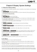
Press the polarity button to select 2400bps, 4800bps, 9600bps, 19200bps, 38400bps, 57600bps, 115200bps, or user-defined,
which users adjust the baud rate by the Multipurpose knob
It is recommended to make reasonable settings based on your RS232 communication hardware and software. Limited by
the basic model of the transmission protocol, the RS232 protocol is usually used in short distance (below 20m) and low
speed (1Mbps) transmission occasions. Communication beyond these ranges can be disturbed easily or become unreliable.
Bit Sequence:
Specify high bytes in front (MSB) or low bytes in front (LSB) to be the data bits of the RS232 protocol signal that needs to
be decoded.
Press PgDn bit sequence to select MSB or LSB.
(1) MSB: The high byte of the data transmits first.
(2) LSB: The low byte of the data transmits first.
Stop Bit:
Press PgDn stop bit to set the stop bit for each frame of data, you can set it to 1 bit or 2 bits.
Parity:
Press PgDn parity to set the parity mode for data transmission, you can choose none, even parity or odd parity.
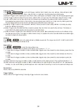
Trigger Condition:
Press PgDn trigger condition to select start of frame, error frame, parity error, and data.
(1) Start of Frame: The waveform trigger is at the start bit of the RS232 protocol (refer to figure). Stable waveforms can be
observed by choosing the start of frame trigger when single string signals or multiple same string signals are sent. If the
data being sent is changing, the waveform will also change correspondingly.
(2) Error Frame: 0 occurs in the stop state or a data error occurs in the middle of the data bits during the receiving process.
(3) Parity Error: Set the RS232 parity bit to 0 or 1 according to the parity principles, the principles are as follows:
Odd Parity: If the total number of 1 in the data bits and parity bits is odd, the transmission is correct.
Even Parity: If the total number of 1 in the data bits and parity bits is even, the transmission is correct.
With this option, you can quickly find the parity errors during the RS232 communication process, which is convenient for
fault analysis and positioning.
(4) Data: Triggers when the data acquired by the oscilloscope is equal to the 2 hexadecimal values set by the user. With this
option, you can quickly find the transmission signal with specific data that you are interested in.
Data:
Valid when the trigger condition is data, it can be 00 ~ FF (hexadecimal number).
Set the data using the Multipurpose knob.
Decode Bus:
Press PgDn decode bus to enter the decode bus menu.
(1) Bus Status: Set the decode bus to on or off.
(2) Display Format: Set the display format of decode bus, you can set hexadecimal, decimal, binary or ASCII.
36
Summary of Contents for UPO2000E Series
Page 1: ...UPO2000E Series Ultra Phosphor Oscilloscope User Manual...
Page 66: ......


