background image

Your safety and the safety of others is extremely important.

We have provided many important safety messages in this 
manual and on your product. Always read and obey safety 
messages.

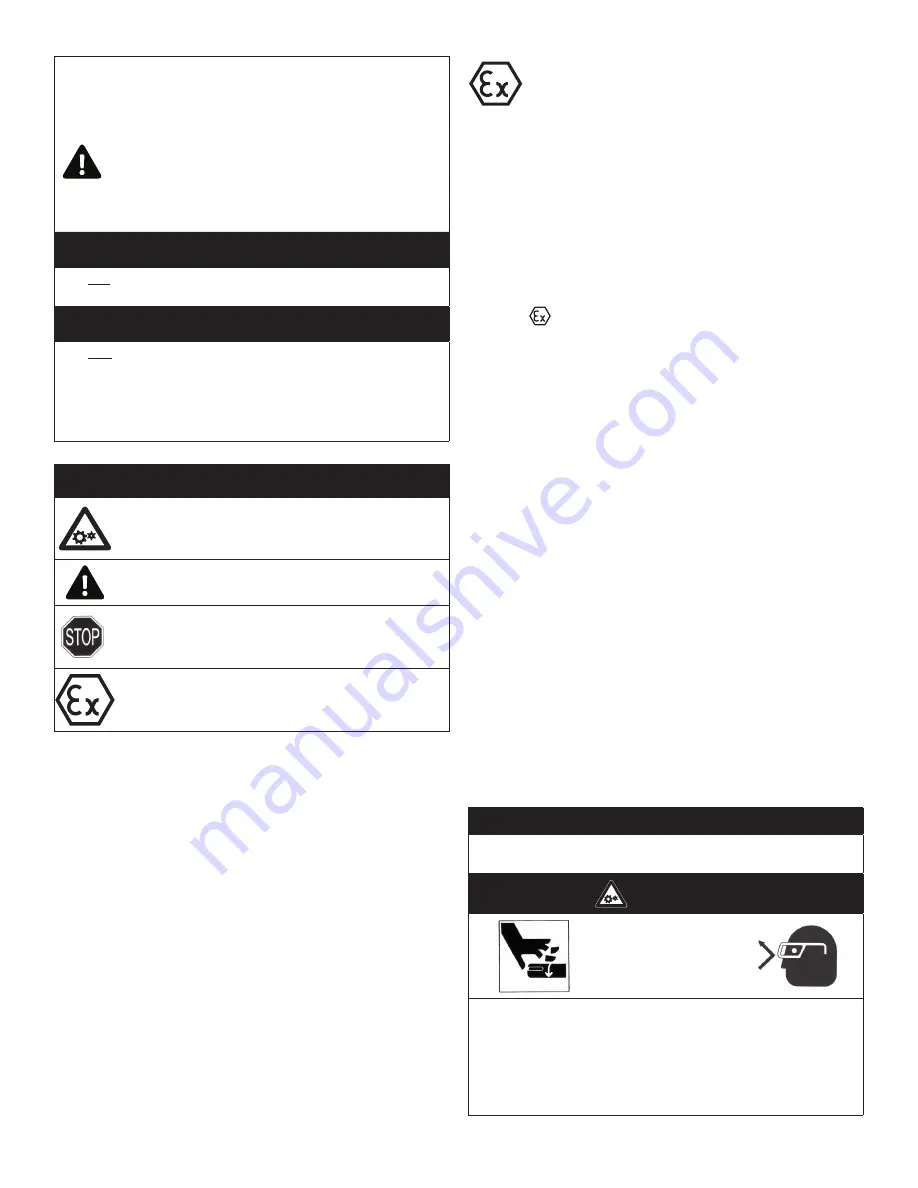
This is the safety alert symbol. This symbol alerts 
you to hazards that can kill or hurt you and others. 
The safety alert symbol and the words “DANGER” 
and “WARNING” will preceed all safety messages. 
These words mean: 

m

 DANGER

You will be killed or seriously injured if you don’t follow 
instructions.

m

 WARNING

You can be killed or seriously injured if you don’t follow 
instructions.

All safety messages will identify the hazard, tell you how to 
reduce the chance of injury, and tell you what can happen if 
the safety instructions are not followed.

CODE SYMBOLS

Hazard. 

Possible consequences: death or severe 

injuries

Hazardous Situation. 

Possible consequences: slight 

or mild injuries

Dangerous Situation. 

Possible consequences: 

damage to the drive or the environment

Important instructions on protection against 
explosion

Improper environment, installation and operation can result 
in severe personal injury and/or damage to property.

Qualified personnel must perform all work to assemble, 
install, operate, maintain and repair air motor.

Qualified personnel must follow:

•  These instructions and the warning and information labels on the

motor.

•  All other drive configuration documents, startup instructions and

circuit diagrams.

•  The system specific legal regulations and requirements.

•  The current applicable national and regional specifications

regarding explosion protection, safety and accident prevention.

Complete the following checklist prior to starting 
installation in a hazardous area. All actions must be 
completed in accordance with Directive 2014/34/EU.

Checklist for installation in hazardous areas:

______

Read air motor label to check that motor has been
designed for use in a hazardous application:
• Haza dous zone
• Haza dous category
• Equipment g oup
•  emperature class
• Maximum surface temperatu es

Example:

Model designation: 1UP-NRV-10
Year manufactured: 2003
       II 2GD
Ex h IIC T4 Gb    
Ex IIIC T135°C Db
Benton Harbor, MI USA
Telephone: 269.926.6171

* Legend

II:  Equipment group II
2:  Equipment category 2
G:  Gas atmospheres
D:  Dust atmospheres
b:  EPL b.
Max. surface temp. 275ºF/135ºC
Ambient range (Ta) +1Cº to +40ºC (34ºF/104ºF)

______

Check the site environment for potentially explosive oils,
acids, gases, vapors or radiation

______

Check the ambient temperature of the site and the
ability to maintain proper ambient temperature.
Ambient range:
Non-hazardous conditions: 34ºF/1ºC to 250ºF/121ºC
Hazardous conditions: 34ºF/1ºC to 104ºF/40ºC

______

Check the site to make sure that the air motor will be
adequately ventilated and that there is no external heat 
input (e.g. couplings). The cooling air may not exceed 
104ºF/40ºC.

______

Check that products to be driven by the air motor meet
ATEX approval.

______

Check that the air motor is not damaged.

INSTALLATION

Correct installation is your responsibility. 

Make sure

you have the proper installation conditions.

m    

WARNING

Injury Hazard

Install proper guards around output shaft as needed.

Air stream from product may contain solid or liquid materi-
als that can result in eye or skin damage.

Wear eye protection when installing this product.

Failure to follow these instructions can result in serious 
injury or property damage.

Revision 11/3/2021

Summary of Contents for ES320AIR

Page 1: ...ATORS MANUAL DIRECT DRIVE PRESSURE WASHER Once the unit has been removed from the box immediately write in the serial number of your unit in the space provided below SERIAL NUMBER_____________________...

Page 2: ...ON 11 WATER SUPPLY 12 UNLOADER 12 THERMAL RELIEF VALVE 12 PRE START INSPECTION PROCEDURES 13 OPERATING INSTRUCTIONS 14 15 PRIMING THE PUMP 14 START UP 14 CLEANING WITH DETERGENTS 15 SHUTDOWN 15 STORAG...

Page 3: ...MPHASIZE SAFETY WARNINGS THAT MUST BE FOLLOWED WHEN OPERATING THIS PRESSURE WASHER ACCOMPANYING THE SAFETY WARNINGS ARE SIGNAL WORDS WHICH DESIGNATE THE DEGREE OR LEVEL OF HAZARD SERIOUSNESS THE SIGNA...

Page 4: ...Complete the following checklist prior to starting installation in a hazardous area All actions must be completed in accordance with Directive 2014 34 EU Checklist for installation in hazardous areas...

Page 5: ...e Connect the sound absorber on the exhaust air port or valve connection Do not add any thrust to the end or side of the shaft when making connections Do not use a hammer on the shaft or connections L...

Page 6: ...ent will help to maintain proper vane performance Flush the motor if it is operating slowly or inefficiently Use only Gast AH255B Flushing Solvent DO NOT use kerosene or ANY other combustible solvents...

Page 7: ...peratetheunitwhenfatigued PS VOEFS UIF JO VFODF PG BMDPIPM PS ESVHT 4 NEVER squeeze the trigger unless securely braced The thrust from the water traveling through the nozzle may be powerful enough to...

Page 8: ...JOH UIF pump to thaw 4 When connecting the water inlet to the water supply mains local regulations of your water company must be observed In some areas the unit must not be connected directly to the p...

Page 9: ...air lines 5VSOJOH the machinery over by hand during adjustment or cleaning might start the motor and machinery with it causing serious injury to the operator 3 Know how to stop the pressure washer and...

Page 10: ...SO JT CFTU TVJUFE GPS VTIJOH EJSU NVE BOE HSJNF 6TFT 8FU TXFFQJOH MFBWFT GSPN XBMLT DVSCT BOE ESJWFXBZT DMFBOJOH TUBCMF PPST XBTIJOH TXJNNJOH pool bottoms degreasing engines 5IF OP MF 5IJT JT B MPX QS...

Page 11: ...equired on some models e Connect the wand assembly to the gun hose assembly 4 Follow the incoming water requirements listed below a Water pressure must be a minimum of 25 pounds per square inch PSI an...

Page 12: ...UIF TZTUFN PRE START INSPECTION PROCEDURES FGPSF TUBSUJOH UIF VOJU QFSGPSN UIF GPMMPXJOH QSPDFEVSFT 1 Check the oil level in the pump and motor 2 Inspect the water inlet strainer Clean or replace if...

Page 13: ...unit during start up Slowly apply air flow to the motor not to exceed 100 psi 7 bar 7 Once the motor has started perform the following procedures with the gun open a Inspect for system oil leaks and f...

Page 14: ...UIF USJHHFS O B fewmomentsadetergent watermixturewillexitthelowpressurenozzle Start spraying the lower portion of the surface being cleaned and move up using long overlapping strokes Applying from th...

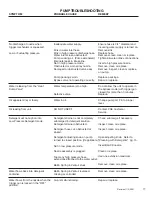
Page 15: ...cement o ring to correct the leak Additional o rings can be purchased from your dealer TROUBLESHOOTING GUIDE Problem Reason and Remedy for Problem Low Torque Low Speed Won t Run Runs Hot Runs Well The...

Page 16: ...ich you are winterizing NOTE Proper winterizing is based on the recommended manufacturer s instructions listed on the Protection Chart shown on the back label of most antifreeze containers f Remove th...

Page 17: ...gun closed for more than 3 minutes Defective valve Replace Oil appears milky or foamy Water in oil Change pump oil Fill to proper level Oil leaking from unit DO NOT USE Contact CSE Customer Service D...

Page 18: ...osive environments or under conditions causing pump cavitation IMPORTANT This unit was designed to be operated in a medium duty application only The use of this washer in any other applica tion will v...

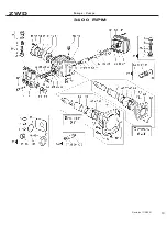
Page 19: ...ZW D Pom pe Pum ps 3 4 0 0 3 4 0 0 RPM r Revision 11 3 2021 19...

Reviews: