Assembly
23
Step 9 Locate the extraction moulding (L), Loosen the two
locking knobs (b) either side of the extraction surround on
the fence (K), slide the extraction moulding (L) over the ‘T’
bolts (d) and retighten the locking knobs (b), see fig 46.
WARNING! DO NOT OVERTIGHTEN THE
LOCKING KNOBS AS THE EXTRACTION
MOULDING IS ONLY PLASTIC!
Fig 46
b
L
Step 10 Locate two ‘T’ bolts (d), fence spacers (c) and flat
washers (i). Slide the ‘T’ bolts into the fence (K) ‘T’ slot and
position the bolts roughly the width of the extraction
moulding (L) and place a fence spacer (c) over the ‘T’ bolt
thread, see figs 47-48.
Fig 47-48
K
d
c
Step 11 Mount the dust shield (M) through the ‘T’ bolts (d),
place a flat washer (i) over the bolts and secure using two
locking knobs (b), see figs 49-50.
Fig 49
M
i
Continues Over...
Summary of Contents for 717127
Page 7: ...What s Included 7 K L M N O P Q a b c d e g h i j N f...
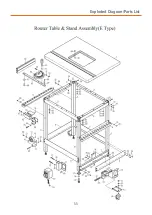
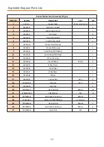
Page 33: ...Exploded Diagram Parts List 33...
Page 38: ...Notes 38...
Page 39: ...Notes 39...


