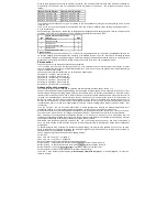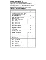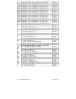
Byte
Bit
0
1
2
3
4
5
6
7
A /
From
Fahr.
Lok fährt
1
/
7
F1
F2
F3
F4
F0
n.b.
Fahr.
Vorw.
2
/
8
F5
F6
F7
F8
F9
F10
F11
F12
Vorw.
Driving direction
forward
3
/
9
F13
F14
F15
F16
F17
F18
F19
F20
n.b.
unused
4
/ 10
F21
F22
F23
F24
F25
F26
F27
F28
5
/ 11
F29
F30
F31
F32
F33
F34
F35
F36
6
/ 12
F37
F38
F39
F40
F41
F42
F43
F44
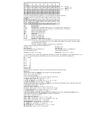
The bits in the respective entries (bytes) 13 - 16 for the output have the following meaning:
Bit
0
1
2
3
4
5
6
7
Byte
13
A1
A2
14
A0v
A0h
S-CLK
S-Data
ABV
ABV2
ABV3
RG
15
A0-P2 A1-P2 A2-P2
16
Cross S-F22 S-F23 S-F24 S-F25 S-F26 S-F27 S-F28
A0v
Front light output
A0h
Rear light output
S-CLK
Output SUSI CLK: (enable A4 logic, CV50 bit4 = 1) or (enable servo1, CV166 bit0 = 1)
S-Data
Output SUSI Data: (enable A3 logic, CV50 Bit4 = 1) or (enable servo2, CV166 Bit0 = 1)
ABV
Starting and braking deceleration 1
ABV2
Starting, braking deceleration 2
ABV3
Starting, braking deceleration 3
RG
Rangiergang
A0-P2
Light outputs, 2nd dimming
A1-P2
Function out1, 2nd dimming
A2-P2
Function out2, 2nd dimming
Cross
CROSS-Bit für PWM-modulierte Ausgänge
S-F22 - S-F28 functions F22 - F28 on the SUSI interface on or off, depending on the result of the conditions set in bytes 1
- 12. The state of these functions, as it is transmitted by the digital control center, is then no longer
transferred to the SUSI interface.
The CV159 must be set accordingly for transfer of F22 - F28 to SUSI.
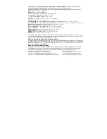
The CV number to be programmed is calculated from the
for lines 1 - 16
for lines 17 - 32
Base value 256
Base value 256
plus (line number minus 1) multiplied by 16
plus (line number minus 17) multiplied by 16
plus the number of the byte.
plus the number of the byte.
Formula:
256 + (line - 1) * 16 + bytes
Formula:
256 + (line - 17) * 16 + bytes
The bit structure and the values to be programmed accordingly in the CVs are comparable to the configuration CVs of the
decoder. This means that there is a fixed value per bit set. If the bit is not set, the value for this bit remains 0.
Bit
Wert
Bit 0
1
Bit 1
2
Bit 2
4
Bit 3
8
Bit 4
16
Bit 5
32
Bit 6
64
Bit 7
128
Summe
255
The values for the individual CVs can now be derived from the above-mentioned information.
Examples:
The output
A1 should
be switched on
when the function key
F1 is
switched on.
Bank 1, line 1 -> CV31 = 8, CV32 = 0
There are two CVs to program
First CV for the power condition (F1 on), second CV for the output (A1 on)
F1 key
on
-> CV number = 256 + (1 - 1) * 16 + 1 = 257
F1 key
on
-> byte 1, bit 0 = 1 -> CV 257 = 1
Output
A1 switched on
-> CV number = 256 + (1 - 1) * 16 + 13 = 269
Output
A1 switched on
-> byte 13, bit 0 = 1 -> CV269 = 1
The light output at the front (
A0v)
should be switched on
when the function key
F0 is
switched on
and the
locomotive is
moving. Bank 1, line 2 -> CV31 = 8, CV32 = 0
There are two CVs to program
Key
F0 on
+
drive -
> CV number = 256 + (2 - 1) * 16 +1 = 273
Key
F0 on
+
drive -
> byte 1, bit 4 = 1 + bit 6 = 1-> CV 273 = 16 + 64 = 80
Output
A0v switched on
-> CV number = 256 + (2 - 1) * 16 + 14 = 286
Output
A0v turned on
-> byte 14, bit 0 = 1 -> CV286 = 1
The starting, braking deceleration 2 (ABV2) and the
output
A2 are to
be switched on
when the locomotive
moves
forward (previous) (driving), not
stationary and
the function F6 is switched on.
Bank 1, line 3 -> CV31 = 8, CV32 = 0
There are four CVs to program
Fahr. + Vorw.
-> CV-Nummer = 256 + (3 - 1) * 16 +1 = 289
Fahr. + Vorw.
-> Byte 1, Bit 6 = 1 + Bit 7 = 1-> CV 289 = 64 + 128 = 192
Key F6 on
->
CV number = 256 + (3 - 1) * 16 +2 = 290
Key
F6 switched on
-> byte 2, bit 1 = 1 -> CV 290 = 2
A2 switched on
-> CV number = 256 + (3 - 1) * 16 + 13 = 301
A2 switched on
-> byte 13, bit 1 = 1 -> CV301 = 2
ABV2 switched on
-> CV number = 256 + (3 - 1) * 16 + 14 = 302
ABV2 turned on
-> byte 14, bit 5 = 1 -> CV302 = 32
.
.
.


