background image

198

Appendix

Appendix1-Error Reporting and Handling

1.1 Joints Error Message and Error Handling

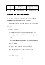
Error processing method: Re-power on, the steps are as follows:

1. Turn the emergency stop button on the control box

2. Enable the robotic arm

UFactory studio enable method: Click the guide button of the error

pop-up window.

850-Python-SDK enable method: Refer to Error Handling Mode.

850-ROS-library: Users can view related documents at

https://github.com/xArm-Developer/xArm_ros

https://github.com/xArm-Developer/xarm_ros2

If the problem remains unsolved after power on/off for multiple

times, please contact UFACTORY team for support.

Summary of Contents for 850

Page 1: ...1...

Page 2: ...Safety Precautions 13 850 User Manual Hardware Section 21 1 Hardware Installation Manual 21 1 1 The Hardware Composition of 850 21 1 2 Robot Installation 25 1 3 Power Supply for the Robotic Arm 34 2...

Page 3: ...ry studio Introduction 77 1 4 Robotic Arm Setting 79 1 5 Live Control 118 1 6 Blockly Graphical Programming 134 1 7 Python IDE 162 2 850 Motion Analysis 164 2 1 Motion of the Robotic Arm 165 2 1 1 Joi...

Page 4: ...50 Common Specifications 209 1 2 850 Specifications 211 Appendix3 FAQ 212 Appendix4 The 850 Software Firmware Update Method 213 1 Online upgrade when PC has network connection 214 2 Offline upgrade wh...

Page 5: ...nd Stopping Distance 222 1 10 Maximum Speed 223 1 11 Specifications 223 Appendix8 DH Parameters of 850 Series 224 Preface Product Information Package contains 1 Robotic Arm x 1 2 Control Box x 1 3 Rob...

Page 6: ...6 5 Robotic Arm end effector adapter cable x1 6 Ethernet Cable x1 7 Ethernet Adapter Cable x1 Main Contents of the Manual 850 User Manual Hardware Section 1 850 hardware installation...

Page 7: ...tions The following terms and definitions apply to this manual Control Box The control box core part of the robotic arm is the integration of the robotic arm control system End Effector The end effect...

Page 8: ...mm Roll Pitch Yaw Roll Pitch Yaw sequentially rotates around the X Y Z of the selected coordinate system base coordinate system The following describes the roll pitch yaw orientation representation o...

Page 9: ...tude representation as unit quaternion q cos phi 2 sin phi 2 x sin phi 2 y sin phi 2 z For example The vector of the rotation axis represented by the base coordinate system is 1 0 0 and the rotation a...

Page 10: ...ty range is from 0 to 5 level When it is set to 0 it means that collision detection is not enabled The larger the set value the higher the collision sensitivity level and the smaller the force require...

Page 11: ...1 and Table 1 2 Table 1 1 Working range of each joint of the robotic arm Table 1 2 Range of various motion parameters of the robotic arm Robotic Arm 850 Maximum 180 s Working Range Joint 1 360 Joint...

Page 12: ...peed is the attitude rotation speed so the range 0 to 1000 corresponds to 0 to 180 s Unit Definition The Python Blockly examples and the units standard in the communication protocol are shown in Table...

Page 13: ...the content with warning signs Due to the complexity of the robotic arm system and its degree of danger please ensure you fully understand the content of this manual and strictly adhere to the instruc...

Page 14: ...ndards and regulations of the country where the robotic arm installed The integrators of the 850 are responsible for the compliance of applicable safety laws and regulations in the country to prevent...

Page 15: ...by UFACTORY that the 850 will not cause injury or damage even if all safety instructions are complied with Safety Alarms in this Manual DANGER This indicates an imminently hazardous electrical situati...

Page 16: ...ontains some general warnings and cautions on installation and application planning for the robotic arm To prevent damage to the machine and associated equipment users need to learn all the relevant c...

Page 17: ...use e g the operational safety and the possible damage of the robotic arm and other device systems 5 Preliminary testing and inspection for both robotic arm and peripheral protection system before pro...

Page 18: ...other machinery it may increase risk and result in dangerous consequences Make sure a consistent and complete safety assessment is conducted for the installation system 1 The robotic arm and Control...

Page 19: ...to unpredictable danger to the integrators The authorized restructuring needs to be in accordance with the latest version of all relevant service manuals If the robotic arm is modified or altered in a...

Page 20: ...arm running error 2 When the device is running even if the robotic arm seems to stop the robotic arm may be waiting for the signal and in the upcoming action status Even in such a state it should be...

Page 21: ...or unstable clamping of the robotic arm 850 User Manual Hardware Section 1 Hardware Installation Manual 1 1 The Hardware Composition of 850 1 1 1 Hardware Composition The composition of robotic arm ha...

Page 22: ...et adapter cable x1 The 850 robotic arm system consists of a base and rotary joints and each joint represents a degree of freedom From the bottom to the top in order Joint 1 Joint 2 Joint 3 etc The la...

Page 23: ...ency stop should not be used as a risk reduction measure When an emergency occurs during the operation of the robotic arm users need to press the emergency stop and the posture of the robotic arm will...

Page 24: ...otic arm click the button Enable Robot Python SDK enable the robotic arm motion_enable true 1 1 3 Control Box Description Control Box Buttons and Indicator Parameter Name Function ROBOT power indicato...

Page 25: ...least 10 times the full torsion of the base joint and at least 5 times the weight of the arm 1 The robotic arm and its hardware composition must not be in direct contact with the liquid and should not...

Page 26: ...azard do not connect or disconnect the robotic arm cable when the robotic arm is connecting with external AC 1 2 2 Robot Installation 1 Brief installation steps a Define a robotic arm workspace b Fix...

Page 27: ...ns and working range of the robotic arm When installing the robotic arm make sure the range of motion of the robotic arm is taken into account so as not to bump into the surrounding people and equipme...

Page 28: ...2 2 2 Robot Installation The robotic arm has four M8 bolts provided and can be mounted through four 8 5 holes in the base of the robotic arm It is recommended to tighten these bolts with a torque of 2...

Page 29: ...nal Cable into the interface of the Robotic Arm The connector is a foolproof design Please do not unplug and plug it violently Plug the Robotic Arm Power Supply Cable and the Robotic Arm Signal Cable...

Page 30: ...interface marked LAN on the Control Box and plug the other end of the Network Cable into the computer 1 2 2 5 End effector Installation The End effector flange has 6 M6 threaded holes and one 6 posit...

Page 31: ...he orientation of the end effector must be documented in a file format to avoid errors and unexpected results when re installing the end effector The end effector flange referenced ISO 9409 1 50 4 M6...

Page 32: ...ll not be able to use this interface temporarily We will develop new accessories in the future and use this interface as a connection Lighting In fact this is a button with an aperture around the butt...

Page 33: ...stability of the system Standard CAT5 Ethernet cable compatible with most third party vision devices You can experiment with using it as a physical signal wire if you want Tool I O At the tool side of...

Page 34: ...on specifications of sharp end effector tools 5 If the installed end effector exceeds the robotic arm mounting surface at the zero position of the robotic arm a safety assessment is required for the z...

Page 35: ...2 Press the power button when the status indicator CONTROLLER lights up the control box is turned on 3 Rotate the emergency stop button in the direction indicated by the arrow and is pulled up at whic...

Page 36: ...off the robotic arm 2 Ensure the power indicator light is off 2 Shutdown the control box 1 Turn off the power supply of the control box The power switch takes about 5 seconds to turn off the power of...

Page 37: ...arm malfunction 2 Electrical Interface 2 1 AC Control Box 2 1 1 Connect the Control Box to the Robotic Arm 1 The robotic arm power supply cable connects the power port of the robotic arm and the ROBO...

Page 38: ...12V 48V DC which supplies power to the load of the control box and the robotic arm Therefore it is necessary to check whether the connection between the robotic arm and the control box is secured bef...

Page 39: ...s the corresponding IEC C19 wire must be used Connect to the standard IEC C20 plug of the Control Box to complete the process see the figure below 2 1 3 Definition of the Robotic Arm Industrial Connec...

Page 40: ...to follow this warning may result in serious injury or death due to an invalid safety stop function 1 Make sure that all the non waterproof equipment is kept dry If water enters the product turn off...

Page 41: ...EMC problems 2 The length of the I O cable that used to connect the Control Box with other mechanical and plant equipment must not exceed 30 meters unless it is feasible after the extension testing 1...

Page 42: ...color represents different functions please refer to the following table Pin sequence Color Signal 1 Brown 24V Power 2 Blue 24V Power 3 White 0V GND 4 Green 0V GND 5 Pink User 485 A 6 Yellow User 485...

Page 43: ...y danger when the power is cut such as dropping of the work piece from the tool 2 3 1 Digital Output The digital output is implemented in the form of NPN with an open collector OC When the digital out...

Page 44: ...power of the resistor depend on the specific use Note It is highly recommended to use a protection diode for inductive loads as shown below 2 3 2 Digital Input The digital input is already equipped wi...

Page 45: ...ut is a non differential input The electrical specifications are as follows Parameter Min Typical Max Unit Input Voltage in Voltage Mode 0 5 3 3 V Resolution 12 Bit Input Current in Current Mode mA Pu...

Page 46: ...how the analog sensor can be connected to a non differential output Voltage mode Current mode 2 3 3 2 Differential Analog Input The following figures show how the analog sensor is connected to the dif...

Page 47: ...ow to connect devices to the electrical I O outside of the control box The I Os are extremely flexible and can be used in many different devices including pneumatic relays PLCs and emergency stop butt...

Page 48: ...7 General Input Yes Yes Stop Moving Yes No Safeguard Reset Yes No Offline Task Yes Yes Manual Mode Yes Yes Reduced Mode Yes No Enable Robot Yes Yes Configurable Function CO0 CO7 DO0 DO7 General Output...

Page 49: ...for I O The default configuration is to use internal power see below If larger current is needed connect the external power supply as shown below The electrical specifications for the internal and ex...

Page 50: ...Type Note For resistive or inductive loads up to 1H 2 4 2 Dedicated Safety I O This section describes the dedicated safety inputs and their configurations of the safety I O Please follow the universal...

Page 51: ...nces are as follows Emergency Stop Protective Stop Stops the motion of the robotic Yes Yes Program execution Stop Suspend Reset Manual Auto or manual Usage frequency Not frequent No limit Need re init...

Page 52: ...cy stop buttons 2 4 2 3 Share Emergency Stop with other Machines When a robotic arm is used with other machines it requires to set up a common emergency stop circuit in most of the time The following...

Page 53: ...et the reset button outside the door as to reactivate the movement of the robotic arm Another example of an automatic recovery is the use of a safety pad or a safety laser scanner see the figure below...

Page 54: ...on reset function with reset button 1 Configure CI0 as the safeguard reset in UFactory studio The specific steps are as follows Enter Settings I O Input Configure CI0 as safeguard reset Save 2 If 850...

Page 55: ...he form of NPN When the digital output is enabled the corresponding connector will be driven to GND When the digital output is disabled the corresponding connector will be open OC OD Users must follow...

Page 56: ...rable Input The digital input is implemented in the form of a weak pull up resistor This means that the reading of the floating input is always high Users must follow the electrical specifications set...

Page 57: ...r can be used device communication see the figure below 2 4 4 General Analog I O This type of interface can be used to set or measure voltage 0 10V going into or out of other devices For the highest a...

Page 58: ...ge Mode AIx AG Voltage 0 10 V AIx AG Resistance 10k AIx AG Resolution 12 12 bit Analog Output under Voltage Mode AOx AG Voltage 0 10 V AOx AG Current 0 20 mA AOx AG Resistance 100k AOx AG Resolution 1...

Page 59: ...sensor Connect to AI0 or AI1 2 5 Communication Interface The Control Box provides Ethernet interface as shown in the figure below 2 6 Ethernet TCP IP The control box provides a gigabit Ethernet interf...

Page 60: ...face If the connection is successful the network port indicator blinks frequently The default network segment IP address of the control box is 192 168 1 2 254 For a specific IP address please check th...

Page 61: ...twork segment and close the computer s network proxy To test whether the computer can communicate with the robotic arm open the command terminal and input ping 192 168 1 the IP address of the robotic...

Page 62: ...per If the clamping is not tight a negative value can be set until it is tightened The speed of the gripper should be in 1000 5000 If a speed less than 1000 was set the gripper may not work The speed...

Page 63: ...ripper with the gripper connection cable Note 1 When wiring the gripper connection cable be sure to power off the robotic arm to set the emergency stop button in the pressed state and to ensure that p...

Page 64: ...ting cable are relatively thin please be careful to avoid bending the male pins during disassembly 3 1 2 The Flow of Gripper Movement 1 Enable the gripper 2 Send out a position for clamping 3 The curr...

Page 65: ...unused suction cup needs to be sealed Note If the surface of the object is not smooth there will be air leakage from the suction cup which makes the object fail to be sucked up firmly Indicator status...

Page 66: ...ction cable be sure to power off the robotic arm to set the emergency stop button in the pressed state and to ensure that power indicator of the robotic arm is off as to avoid robotic arm failure caus...

Page 67: ...vacuum_gripper False wait False Turn off vacuum gripper Note 1 Python SDK and UFactory studio provide wrapped functions that can be called to turn on off the vacuum gripper 2 For detailed instructions...

Page 68: ...drop the code blocks of Blockly UFactory studio allows users to plan the motion trajectory for the robotic arm without programming skills Note 1 Installation systems supported by the UFactory studio c...

Page 69: ...studio you must ensure that the hardware is installed correctly and all the protective measures for the workplace environment have been implemented 1 The robotic arm is fixed on the plane protective...

Page 70: ...work is connected If the network indicator in the middle of the control box flashes frequently it means the network communication is normal 6 Check if the robotic arm is powered and the emergency stop...

Page 71: ...ol box PC and router are connected by Ethernet cable 3 PC and router are connected by wireless network and control box an d router are connected by Ethernet cable Note It is not recommended because of...

Page 72: ...72 4 The control box PC and network switch are connected by Ethernet ca ble...

Page 73: ...factory the default IP address is 192 168 1 xxx The factory IP address of the device has been marked on the side of the control box Therefore to successfully communicate with the control box the IPV4...

Page 74: ...74 Step3 Open the Properties Step4 Open the IPV4...

Page 75: ...the same as the IP address of the control box If not please modify the computer s IP Step6 1 2 3 Connect to the Robotic Arm There are the following two ways to communicate with the robotic arm 1 If yo...

Page 76: ...efault IP address of the device has been marked on the side of the control box 2 If you use a browser to access UFactory studio you can communicate with the robot through the following steps 1 Open th...

Page 77: ...Factory studio mainly consists of 3 main functional modules Live Control Used to control the position of the robot arm in real time adjust the motion attitude of the robot arm end tool and track recor...

Page 78: ...ow drop down menu or adjust the size by dragging the border of the window Language Switch language in the upper right corner of the toolbar Language may switch between Simplified Chinese English Tool...

Page 79: ...the actual situation 1 4 1 Motion Settings 1 4 1 Parameters 1 4 1 1 Joint Motion Acceleration The acceleration of joint motion The larger the value the less time it takes to reach the set speed The ra...

Page 80: ...ntrol Attitude step Set the step length for fine adjustment of TCP orientation in Live control 1 4 1 3 Collision Detection When the deviation of the torque detected by the joint exceeds a certain norm...

Page 81: ...ty but it is not recommended to lower it to less than 3 1 4 1 4 Initial Position Setting the Initial Position of the robotic arm can help the user to return the robotic arm to a relatively safe positi...

Page 82: ...payload in mm this position is expressed in default TCP coordinate located at flange center Frame B in the above figure If there is virtually no load at the end both TCP payload and centre of gravity...

Page 83: ...can be set and the additional TCP payload data can be recorded The additional TCP payload data can be referenced during Blockly programming Set as default Set the payload data to the payload of the cu...

Page 84: ...o create a new TCP payload Manual input or Automatic identification Manually inputting can be selected if the weight of the payload and the approximate center of gravity of the payload are known The c...

Page 85: ...gs click Next to start the TCP offset settings When creating a new TCP offset there are two ways to set the new TCP offset parameters as shown in the figure below 1 Manual Input When the TCP offset pa...

Page 86: ...ters by teaching 5 points Delete Delete the selected offset data Note the current default offset data cannot be deleted Save Save for the newly added offset record setting the default offset and delet...

Page 87: ...stomize the user coordinate system X Y Z are coordinate values that are offset relative to the base coordinate system Roll Pitch Yaw represents the angular values of orientation relative to the base c...

Page 88: ...rdinate offset parameters as shown in the figure below 1 Manual Input When the base coordinate offset parameter is known you can choose to manually input its base coordinate offset parameter 2 Teachin...

Page 89: ...89 Cancel Cancel the selection Save Save the modified data Discard Discard the modified data...

Page 90: ...C in coordinate system A As figure shown the offset of the base coordinate system should be 1000 0 0 0 0 180 Former TCP coordinates of B 207 0 112 180 0 0 in base coordinate system after user coordin...

Page 91: ...tion of gravity When the deviation between the installation direction you set and the installation direction detected by the IMU exceeds 10 the software will pop up prompts Floor 0 0 The default metho...

Page 92: ...d rotation angle The initial position of the robotic arm On the horizontal plane when the user is facing the robotic arm side the initial position is on the left hand side of the user in a downward di...

Page 93: ...point your thumb in the direction of the robotic arm which is vertically mounted The direction where your four fingers point is the positive direction and vice versa The range of rotation angle 180 Ma...

Page 94: ...O Settings The control box of the robotic arm is equipped with 32 digital input and output signals which can be set in the Blockly project and SDK only when IO is set to General Input Output otherwise...

Page 95: ...ler input is set as a general input otherwise it will cause a function conflict For example if CI 0 is configured as an offline task CI 0 should not be used in any program Stop Moving Trigger IO the r...

Page 96: ...lete the project Manual Mode When set as Manual Mode the robotic arm can be dragged freely when the input signal remains low level Reduced Mode The IO is triggered and the robotic arm enters the reduc...

Page 97: ...neral output otherwise it will cause function conflict For example if CO 0 is configured as motion stopped CO 0 should not be used in any program Motion Stopped The system enters an emergency stop sta...

Page 98: ...the output is high Collision When the robotic arm reports an error of collision the output is high Manual mode When the Manual Mode is turned on the output is high Offline task running When the roboti...

Page 99: ...Input Monitor Output Monitor In this interface the IO input status and IO output status of the control box can be monitored and the IO output status of the control box can be controlled by clicking t...

Page 100: ...o do load recognition of the torque sensor and set the manual mode direction of the torque sensor 1 4 2 3 Modbus RTU In the Modbus RTU interface the user can send commands to control the robot gripper...

Page 101: ...gram will do CRC checksum automatically 4 Click Send and you can see the sent and received information in the debug box on the left If you want to send in a loop you need to set the delay time turn on...

Page 102: ...m back into the restricted space Reduced Mode When this mode is turned on the maximum linear speed maximum joint speed and joint range of the robotic arm in Cartesian space will be limited 1 4 4 Gener...

Page 103: ...Factory studio Live Control page The left side of the figure below is the axis angle control the button is displayed as Rx Ry Rz the right side is the R P Y control and the button is displayed as R P...

Page 104: ...er the guidance of technical support Please contact the technical support by the email support ufactory cc In this interface you can get the joint current value and joint voltage value of the robotic...

Page 105: ...e joint can be dragged by hand to rotate After confirming the position please re lock all the joints manually Note 1 Please ensure to hold the robotic arm by hand when unlocking the joint to prevent i...

Page 106: ...he robotic arm When releasing the joint brakes someone must support the robot s posture to prevent the robotic arm from falling without external force and damage the robotic arm and surrounding equipm...

Page 107: ...l Output will be set to the invalid state Otherwise the Controller Digital Output or Tool Digital Output will not be affected by the stop command Collision Rebound When this mode is turned on the robo...

Page 108: ...robotic arm as a configuration file The robotic arm parameters that can be exported mainly include motion parameters TCP offset TCP payload IO settings safety boundary installation methods coordinate...

Page 109: ...When the control box fails and needs to be repaired you can export and save the configuration file of the robotic arm to prevent the original data from being lost or changed during the repair process...

Page 110: ...he jerk cannot be modified 3 If an error warning occurs on the robotic arm the jerk cannot be modified 4 When the robotic arm is moving the jerk can not be modified On this page you can view all the p...

Page 111: ...f the arm and the UFactory studio software version the degree of freedom number of axis of the current robotic arm and SN address of the robotic arm can be checked Network Settings Display the IP addr...

Page 112: ...op button and turn off the power of the control box 2 Connect RI0 to GND with a cable 3 Turn on the power of the control box After hearing the sound of beep it means that the IP address of the control...

Page 113: ...rm 6 If you need to modify the IP just modify the IP in Settings System Settings Network Settings For example the modified IP is 192 168 1 54 7 Restart the control box enter your modified IP in the UF...

Page 114: ...me you restart the control box no matter what IP address you modify the IP address of the control box will be automatically changed to 192 168 1 111 so after modifying the IP Be sure to unplug the cab...

Page 115: ...pressing the Power button of the control box and the shutdown process takes 2 to 3 seconds Reboot Click this button the control box of the robotic arm will restart After the restart action is complete...

Page 116: ...the control box can communicate with external internet Click to get the latest UFactory studio and 850 firmware version information for your controller Install Click to go to the offline installation...

Page 117: ...117 1 4 5 3 Log The error log of the control box servo error log and end effector error log can be checked Click the Download button to download the error log...

Page 118: ...f the currently linked robotic arm controller o Payload Displays the current default load parameters of the arm Robotic arm status o Normal The robotic arm is not in motion but is ready to go into mot...

Page 119: ...ulation robotic arm It means the robotic arm is connected and the current one is simulation robotic arm You can control the virtual robot arm movement through UFactory studio interface o Real arm mean...

Page 120: ...he robot arm return to zero point attitude You can set the initial point by clicking Settings Motion Parameters Initial Point Position in the home page Initial point point press for step motion long p...

Page 121: ...ers can control the motion of the robotic arm based on the base coordinate system and TCP coordinate system The trajectory of tool center point in the Cartesian space is a straight line Each joint per...

Page 122: ...dinate System The default TCP coordinate system is defined at the centre point of the end flange of the robotic arm and it is the result of rotating 180 0 0 around the X Y Z axis of the base coordinat...

Page 123: ...rm moves in the direction of angle If the robotic arm needs to be moved in the direction of the angle a new position between the angles of should be inserted and the angle that formed by the inserted...

Page 124: ...tion 1 5 3 3 Speed Setting It is used to adjust the motion speed of the live control interface of 850 Note that the maximum speed of the live control interface is not the actual maximum motion speed o...

Page 125: ...tween joint command TCP Operating Speed The Cartesian speed range is from 1mm s to 1000mm s The actual maximum speed is also affected by the payload speed and posture of the robotic arm If the set spe...

Page 126: ...e Display X Y Z represents the coordinates of the tool center point TCP position of the robotic arm under the base coordinate offset Roll Pitch Yaw under the Attitude indicates the angle value rotated...

Page 127: ...on the homepage Aligning the Hand After clicking this button the tool flange will be adjusted to a horizontal attitude that is pitch and roll will be adjusted to the fixed values of 0 and 180 1 5 3 J...

Page 128: ...current joint and its degree Operation mode Click or for the step angles users can set the step angle in Settings Motion Settings Joint Motion Joint Step Press and hold or for continuous joint motion...

Page 129: ...on trajectory thereby reducing the development workload When danger occurs you can also use the manual mode to manually drag the robot away from the danger zone Drag sensitivity can be set in Joint Co...

Page 130: ...fore Manual Mode can be turned on The SN of the control box can be checked in Settings My Device Device Info 3 The SN address of the robotic arm can be checked next to the power signal interface of th...

Page 131: ...dragged directly for trajectory recording When starting recording be sure to pay attention to the load state of the robotic arm so as to avoid the big difference between the actual load and the set lo...

Page 132: ...ently supported by 850 are 850 Gripper 850 vacuum Gripper 850 BIO Gripper Robotiq 2F 85 Gripper Robotiq 2F 140 Gripper Take the 850 Gripper as an example 850 Gripper When installing other end effector...

Page 133: ...se a 3D model cylinder cuboid that can wrap the end effector and use it as the self collision prevention model of the end effector When no end effector is installed at the end of the robotic arm selec...

Page 134: ...ng and dropping code blocks without the need to write the code manually 1 6 1 Interface Overview Project Click to expand to display all created items the currently open item xxx is displayed when it f...

Page 135: ...kly file Rename Click to rename the selected Blockly file Delete Click to delete the selected Blockly file Upload the Blockly file saved on the computer to the control box of the 850 Run the Blockly p...

Page 136: ...f the virtual robotic arm 1 6 2 Blockly Workspace Drag the code block into the action panel the code execution is top down users can drag and drop the code block with the blocks attached from behind t...

Page 137: ...blank workspace of the non code block the function is mainly for all code blocks Undo Undo the previous operation Redo Restore the last undo operation Collapse Blocks Collapse all code blocks Expand B...

Page 138: ...ther files Add Comment Users can add a description to the code block which is identified by the symbol Click to open close the description pop up window as shown in the following figure External input...

Page 139: ...osition click edit Then the robotic arm will move to the current position and open the live control interface Wait true false indicating whether to wait for the execution of a command before sending t...

Page 140: ...ands such as multiple loops infinite loops and breaking loops Math Contains commands for mathematical operations Advanced Includes location notes and message reminders 1 6 4 Setting Set TCP speed mm s...

Page 141: ...tcp offset X Y Z R P Y Set the end offset of the current project reference Settings TCP Offset from the drop down list Set world offset X Y Z Roll Pitch Yaw Set the base coordinate offset of the curre...

Page 142: ...ainly used in motion programs that need to do the continuous motion It is used to buffer more motion commands for successful continuous motion calculation Motion With this command operators can set th...

Page 143: ...oordinate target value of the linear motion and the TCP rotation angle in mm and Move front back left right true false mm Indicates that the robotic arm makes relative linear motion forward backward l...

Page 144: ...Note To achieve smooth track motion you need to set Wait false move joint variable J1 J2 J3 J4 J5 J6 J7 Wait true false The command passes through the joint motion and supports variable values move ar...

Page 145: ...145 1 6 6 GPIO Control Box and End tool interface...

Page 146: ...ations The control box has 8 digital input interfaces 8 digital output interfaces 2 analog input interfaces and 2 analog output interfaces The end tool has 2 digital input interfaces and 2 digital out...

Page 147: ...ic location X Y Z represent the coordinate value of the specified position to be reached by the robot arm with the unit of mm The digital IO is triggered as soon as the system detects that the TCP pos...

Page 148: ...ition are IO trigger logic of UFactory studio 1 UFactory studio obtains the IO state every 100ms and uses the IO state value obtained for the first time as the initial value 2 Compare the IO state obt...

Page 149: ...149 1 6 7 End Effector...

Page 150: ...and closing speed of the gripper set bio gripper Speed Wait true false move edit Set the opening and closing speed of the gripper set robotiq gripper Pos Speed Wait true false move edit Set the posit...

Page 151: ...of the command and execute the next command get 850 vacuum gripper state Obtain whether the vacuum gripper picks the object or not When the vacuum gripper state is 1 it indicates that the object is p...

Page 152: ...152 1 6 8 Application Run Trajectory path Times 1 Users can import the trajectory recording file and set the times of executions Import other APP Users can import Blockly of other projects...

Page 153: ...ait Wait for the next command to be sent with the unit of seconds if Condition 1 Run Command 1 If Condition 1 is true then Command 1 will be run Otherwise it will be skipped The setting method of the...

Page 154: ...ill pop up a selection box as shown below 2 At this point drag the else code block to the bottom of the if code block and combine the two code blocks as shown below 3 Click the setting button the sele...

Page 155: ...d contained in the loop will be executed in infinite loop repeat times do The command contained in the loop will be executed X times repeat while until do When the condition is not met it jumps out of...

Page 156: ...156 1 6 11 Math You can use the above code block to do some complex operations such as addition subtraction multiplication and division exponential operations...

Page 157: ...an indicator and can change the color message type Types available are information success warning error duration indicates the time interval the message is displayed the unit is in second the message...

Page 158: ...ded variable and set the font and the color Date The date and time on which the command was run can be output Python Code You can write custom python code to turn it into a block in Blockly and use it...

Page 159: ...lete variable Delete the variable 1 6 14 Function to do something Users can define a new function without a return value to do something return Users can define a new function with a return value if r...

Page 160: ...Edit Motion Coordinates Long press Move button to move the robotic arm to the position of the current command Click edit to pop up the live control interface to re edit the motion coordinates of the c...

Page 161: ...int A to point C a safety assessment must be carried out to avoid damage to peripheral facilities Due to the complexity of Cartesian commands Cartesian spatial trajectory planning needs to be solved b...

Page 162: ...before moving again to prevent collisions When the robotic arm is in certain positions there may be a situation where the linear motion is unsolvable At this time the route needs to be re planned For...

Page 163: ...e Import Click to import local Python files Download Click to download the selected Python file Rename Click to rename the selected Python file Delete Click to delete the selected Python file Run the...

Page 164: ...fer amount 2048 a warning code will be returned The warning code is decimal 11 and the command will be discarded The commands issued should not exceed 256 command caches It is recommended to keep the...

Page 165: ...radian False 3 arm xArmAPI 192 168 1 226 is_radian True When the xArmAPI interface is created in method 1 the default value of is_radian is False the unit is When the xArmAPI interface is created in m...

Page 166: ...3 J4 J5 J6 J7 Radius Set each joint angle for the joint movement the unit is Wait true false indicates whether to wait for the execution of this command before sending the next command Move The roboti...

Page 167: ...t joint angle for joint motion parameter servo_id joint ID 1 7 None or 8 means all joints a 1 Number of axes Joint number of the robotic arm E g arm set_servo_angle servo_id 1 angle 45 is_radian False...

Page 168: ...yaw is degree wait If wait True wait for the current commands to finish before sending the next commands If wait False send the next commands directly mvtime 0 reserved Note 1 If the joint angle is t...

Page 169: ...ng the radius of the transition arc R 60mm which is used to achieve a smooth transition of the arc in a joint motion The parameters of Radius can be set as Radius 0 Radius 0 Radius 1 different paramet...

Page 170: ...t the turn this speed will not be continuous between this and next motion as shown in the figure below speed will decelerate to 0 at point B before moving to C Note Radius 0 cannot realize continuous...

Page 171: ...of the robotic arm based on the base coordinate system and TCP coordinate system The trajectory of tool center point in the Cartesian space is a straight line Each joint performs a more complex moveme...

Page 172: ...t motion may exceed its maximum speed and acceleration limits Blockly example Set TCP speed mm s Set the speed of the linear motion in mm s Set TCP acceleration mm s Set the acceleration of the linear...

Page 173: ...ition Description Sets the Cartesian coordinate value of the linear motion Parameter x coordinate x unit mm y coordinate y unit mm z coordinate z unit mm roll attitude roll default unit is Unit if is_...

Page 174: ...Note If it is 8505 roll and pitch must be set to roll 180 and pitch 0 2 1 1 2 Arc Linear Motion Characteristics of Arc Linear Motion Arc linear motion Lineb inserting arc transitions between two stra...

Page 175: ...straight motion The parameters of Radius can be set as Radius 0 Radius 0 Radius 1 different parameters correspond to different trajectories 4 Radius 0 For example setting Radius 5 the turning trajecto...

Page 176: ...this and next motion as shown in the figure below speed will decelerate to 0 at point B before moving to C Note Radius 0 cannot realize continuous motion If you need to plan a continuous movement of t...

Page 177: ...erface is described in Table 2 3 Table 2 3 set_pause_time description set_pause_time Description Set the robotic arm pause time Parameter sltime pause time unit second s wait whether to wait default i...

Page 178: ...otion trajectory of the robotic arm is 2 The center angle 360 the movement track of the robotic arm is a complete circle 3 If you want to draw multiple circles continuously for example draw 10 circles...

Page 179: ...gle Indicates the degree of the circle When it is set to 360 a whole circle can be completed and it can be greater than or less than 360 Note To achieve smooth motion you need to set Wait false Exampl...

Page 180: ...sition 300 0 0 0 400 0 0 0 90 0 180 0 speed 300 mvacc 2000 radius 1 0 wait True move_circle 350 0 50 0 400 0 180 0 90 0 0 0 350 0 50 0 400 0 180 0 90 0 0 0 1000 0 speed 300 mvacc 2000 wait True set_se...

Page 181: ...commands to be sent before sending the next commands If wait False send the next commands directly 2 3 Singularity 1 Concept Singularities occur when the axes of any two joints of a robotic arm are on...

Page 182: ...cannot be explicitly translated into joint motions of each axis When the robot performs motion planning linear circular etc excluding joint movements near the singularity point it will stop to avoid...

Page 183: ...ion and attitude of the robot and re plan the path to the target point Note It is important to consider the cylindrical volume directly above and directly below the base of the robotic arm when a moun...

Page 184: ...184 3 Typical Examples There are 10 examples built into Blockly in UFactory Studio which you can refer to for programming Here are some of the more representative examples...

Page 185: ...ripper to suck the target object at the specified position and then place the target object at the target position Explanation of main commands object is picked release Detect whether the vacuum gripp...

Page 186: ...not it will jump out of the entire program object detection false do not detect whether the object is sucked Cyclic motion count By adding Counter plus each time the command is run the counter of the...

Page 187: ...3 2 The Use of 850 Gripper The role of this program execute this program to control the gripper to grip the target object at the specified position and then place the target object at the target posit...

Page 188: ...188 3 3 The Use of the Digital IO The role of this program If you need to use digital IO to control the motion of the robotic arm you can trigger the digital IO to perform the corresponding motion...

Page 189: ...after startup Joint Motion to achieve the point to point motion of joint space unit degree radian the speed between each command is discontinuous Click to see code set_servo_angle Linear Motion to ac...

Page 190: ...and parameter 2 Click to see code move_circle Mode 1 Servoj mode Servoj motion move to the given joint position with the fastest speed 180 s and acceleration unit degree radian This command has no bu...

Page 191: ...g this mode requires detailed position planning for each axis and motion estimation of the robotic arm which is difficult to develop Click to see code set_servo_angle_j Servo_cartesian motion move to...

Page 192: ...nsiderations do not give a distant target position at once It is recommended that the frequency of user issuing commands be controlled within the range of 30 Hz 250 Hz If the frequency is lower than 3...

Page 193: ...playback_trajectory Mode 4 Joint velocity control mode Click to see code vc_set_joint_velocity Mode 5 Cartesian velocity control mode Click to see code vc_set_cartesian_velocity Mode 6 Joint online t...

Page 194: ...nline planning mode can only use the base coordinate system as the reference coordinate system not the tool coordinate system for relative motion Click to see code mode 7 Operators who design the robo...

Page 195: ...respond to and execute motion commands If the robotic arm recovers from an error power outage or stop state state 4 remember to set the state to 0 before continuing to send motion commands Otherwise...

Page 196: ...ic arm is set to pause state and the motion commands buffer may not be empty State 4 Stopping This state is the state entered by default upon power on Stop and on commands can be executed until state...

Page 197: ...197 State 6 Stop Generally use studio will generate state 6 and state 6 is also a kind of stop...

Page 198: ...2 Enable the robotic arm UFactory studio enable method Click the guide button of the error pop up window 850 Python SDK enable method Refer to Error Handling Mode 850 ROS library Users can view relate...

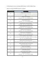
Page 199: ...int Overspeed Please restart the 850 with the Emergency Stop Button on the 850 Control Box S14 Position Command Overlimit Please restart the 850 with the Emergency Stop Button on the 850 Control Box S...

Page 200: ...ad of 850 and whether the acceleration value is too large S26 Joint N Positive Overrun Please check if the angle value of the joint N is too large S27 Joint N Negative Overrun Please check if the angl...

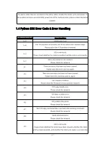
Page 201: ...n If the problem remains unsolved after power on off for multiple times please contact technical support 1 2 Control Box Error Code and Error Handling 1 2 1 Control Box Error Code If there is an error...

Page 202: ...ematic Error Please re plan the path C22 Self collision Error Please Re plan the Path If the robotic arm continues to report self collision errors please go to the live control interface to turn on th...

Page 203: ...the collision sensitivity C32 Three point Drawing Circle Calculation Error please reset the arc command C33 Controller IO Error If the error occurs repeatedly please contact technical support C34 Reco...

Page 204: ...and whether the power is normal C53 Six axis Force Torque Sensor Overload Please reduce the payload or applied external force C110 Robot Arm Base Board Communication Error Please contact technical sup...

Page 205: ...he steps are as follows all the following steps are needed 1 Re powering the robotic arm via the emergency stop button on the control box 2 Enable the robotic arm a UFactory studio enable method Click...

Page 206: ...e click OK to re enable the Gripper G20 Gripper Driver IC Hardware Error Please click OK to re enable the Gripper G21 Gripper Driver IC Initialization Error Please click OK to re enable the Gripper G2...

Page 207: ...nnect Please check the network A1 There are errors that have not been cleared Please clear the errors and try again A2 There are warnings that have not been cleared Please clear the warnings and try a...

Page 208: ...s not enabled For alarm codes that are not listed in the above table enable the robotic arm and gripper If the problem remains unsolved after power on off for multiple times please contact technical s...

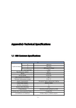
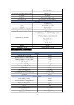
Page 209: ...850 mm Repeatability 0 02 mm Max Speed of End effector 1 m s Ambient Temperature Range 0 50 C Power Consumption Min 20 W Typical 200 W Max 1000 W Input Power Supply 48V DC 20 8A ISO Class Cleanroom 5...

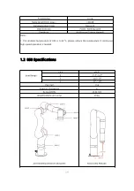
Page 210: ...ster 1 RS 485 Slave Weight 4 8 kg Dimension L W H 376mm 145mm 130mm 850 accessories parameters Gripper Nominal Supply Voltage 24V DC Absolute Maximum Supply Voltage 28V DC Quiescent Power Minimum Powe...

Page 211: ...ormal Notes 1 The ambient temperature of 850 is 0 50 C please reduce the temperature if continuous high speed operation is needed 1 2 850 Specifications Joint Range 1 4 6 360 2 118 120 3 225 11 5 97 1...

Page 212: ...he UFactory studio 4 Solve the problem that all joints of the 850 are at 0 in the gazebo 5 The Method of the IP Configuration 6 How to use PLC to control 850 7 Guide to control 850 by tablet 8 The Pro...

Page 213: ...14 Guide to run 850 at the maximum speed Appendix4 The 850 Software Firmware Update Method Notes 1 It is recommended to update the 850 firmware and UFactory studio at the same time 2 Please check the...

Page 214: ...st SDK code from GitHub Manual download https www ufactory cc download SDK https github com xArm Developer 1 Online upgrade when PC has network connection Use UFactory Studio to do the online upgrade...

Page 215: ...e UFactory Studio to do offline upgrade Go to My Device Check Update click Install to load the offline package downloaded in advance reboot the system it will take 2 3 minutes Appendix5 Maintenance an...

Page 216: ...to be enabled 2 Clean After the robotic arm is used for a long time there may be dirt or grease on the carbon fiber shell in rare cases a small amount of grease can be seen at the joints which will n...

Page 217: ...ranty and returns 3 The general process of after sales service is 1 Contact UFACTORY technical support support ufactory cc to confirm whether the product needs to repair and which part should be sent...

Page 218: ...ct the product during the transportation 2 If you need to send the control box to get repaired please export and save the configuration file of the robotic arm to prevent the original data from being...

Page 219: ...tandards Immunity for industrial environments Part 6 4 Generic standards Emission standard for industrial environments These standards define requirements for the electrical and electromagnetic distur...

Page 220: ...nts for safety related functions Conforming to this standard ensures that the safety functions of 850 robots provide safety even if other equipment exceeds the EMC emission limits defined in the IEC 6...

Page 221: ...e securely tightened at the base of the robot The controller box shall be lifted by the handle Save the packaging material in a dry place you may need to pack down and move the robot in the future 1 5...

Page 222: ...put of the Control Box Performs a Stop Category 1 Emergency Stop Button of the Three Position Enabling Device Performs a Stop Category 1 Three Position Enabling Device Performs a Stop Category 2 Safeg...

Page 223: ...e tests for Joint 2 and 3 the robot followed a vertical trajectory i e the axes of rotation were parallel to the ground and the stop was performed while the robot was moving downwards Stopping Distanc...

Page 224: ...DC Control Box Model AC15 Size L W H 376mm 145mm 130mm I O Ports 8 CI 8 DI 8 CO 8 DO 2 AI 2 AO 2 RS 485 Communication Protocol Private TCP Weight 4 8kg Operating Temperature 0 50 C Humidity 25 85 non...

Page 225: ...direction is pointing out of the viewing surface White dot This means the direction is pointing into the viewing surface Please note the provided Dynamic Parameters are just for reference 1 UFACTORY...

Page 226: ...226 Kiematics i 1 ai 1 mm di mm i Joint1 0 0 364 0 Joint2 90 0 0 90 Joint3 180 390 0 90 Joint4 90 150 426 0 Joint5 90 0 0 0 Joint6 90 0 90 0...

Page 227: ...ACTORY 850 Standard D H Parameters Manufacturer UFactory Technology Co Ltd Kiematics i ai mm di mm i Joint1 90 0 364 0 Joint2 180 390 0 90 Joint3 90 150 0 90 Joint4 90 0 426 0 Joint5 90 0 0 0 Joint6 0...

Page 228: ...228 Address 2F Building M 6 Ma Que Ling Industrial Zone Nanshan District Shenzhen Guangdong China Website www ufactory cc...

Reviews: