MAX-M10M - Integration manual
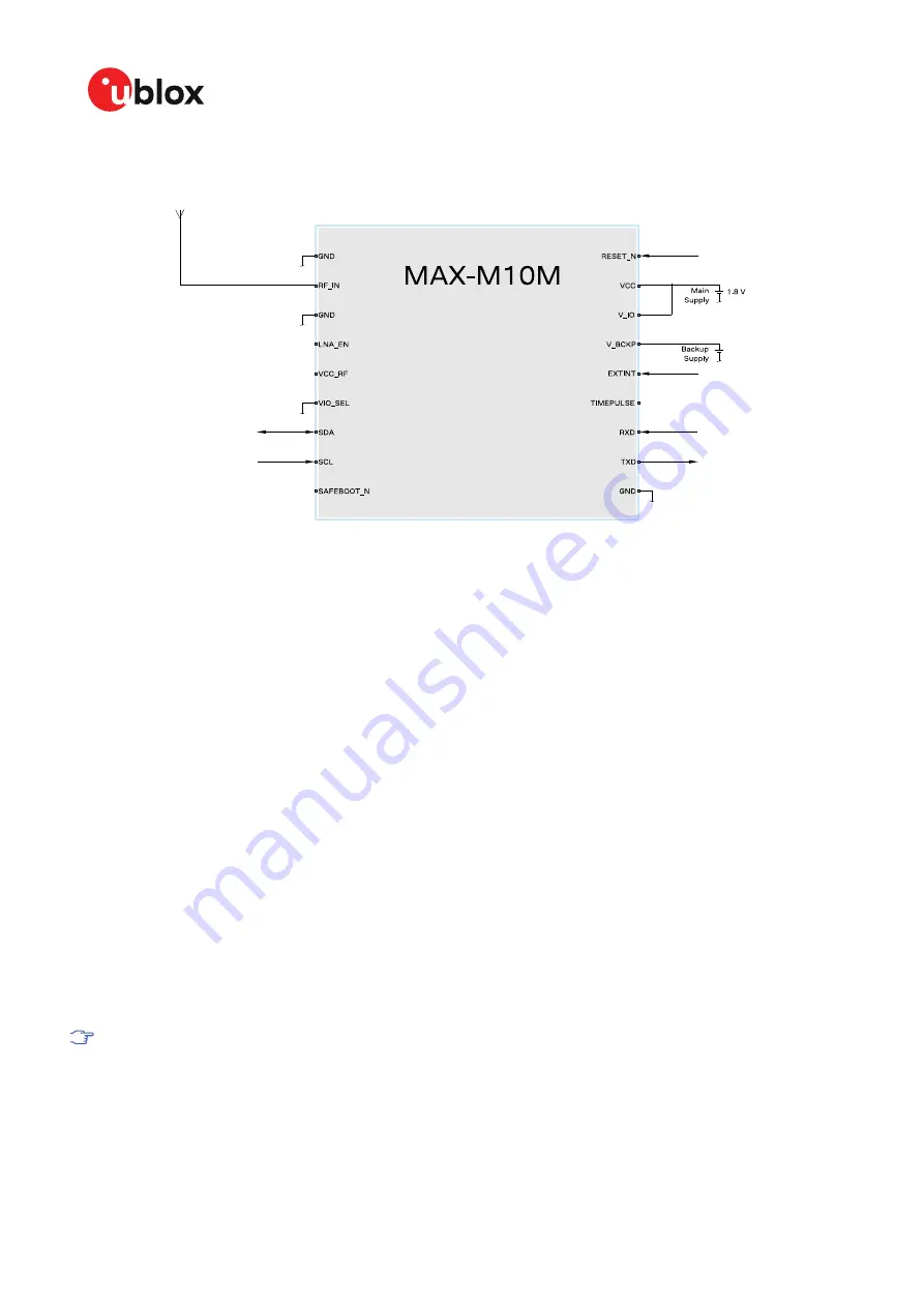
Figure 37: Typical 1.8 V design
B.2 Antenna supervisor designs
show a reference design for a 2-pin and 3-pin antenna supervisor design
respectively. Here are some key features:
• VCC and V_IO are connected together to a single supply.
• Supply at V_BCKP is optional. If present, the hardware backup mode is supported. This mode
maintains the time and GNSS orbit data in the battery-backed RAM memory if the main supply
is switched off.
If there is no backup supply, time aiding with the UBX-MGA-INI-TIME_UTC message (optionally
with a timing signal at the EXTINT pin) and the GNSS orbit data from the AssistNow services or
stored on the host controller can be used to reduce the TTFF.
• An active antenna can be supplied with the VCC_RF output from MAX-M10M or from an external
supply. VCC_RF is a filtered output voltage supply, which outputs VCC - 0.1 V. In addition, the
active antenna supply can be turned on/off by the LNA_EN signal.
• External open drain buffers and operational amplifiers are also needed depending on whether a
2-pin or 3-pin antenna supervisor design is used.
• UART and I2C communication interfaces are available. I2C PIOs (SDA and SCL) can be used in a
3-pin antenna supervisor design as shown in
. In this case, the I2C interface needs to be
disabled before assigning the new function to the PIOs.
Disable the I2C interface with the CFG-I2C-ENABLED configuration key when I2C pins are used
for antenna supervisor functions. Likewise, disable the UART interface (CFG-UART1-ENABLED)
or TIMEPULSE (CFG-TP-TP1_ENA) when the pins are used for antenna supervisor functions.
UBX-22038241 - R02
Appendix
Page 86 of 92
C1-Public


