102
UBI EasyCoder 501 – Technical Manual
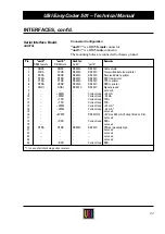
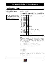
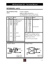
Connector configuration
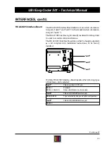
The connector is the standard female 36-pole Centronics type. The
mounting holes are connected to chassis ground.
Note:
The PE signal (Paper End) on pin 12 requires an error-trapping
routine to be included in the UBI Fingerprint software, activating
the
BUSY
and
READY
statements. Here is an example on how such
a routine may be written:
10
IF (PRSTAT AND 4) THEN GOSUB 1000
20
IF (PRSTAT AND 4) = 0 THEN GOSUB 2000
. . . .
. . . .
. . . .
1000 BUSY4
1010 RETURN
2000 READY4
2010 RETURN
Also see
BUSY
and
READY
statements and
PRSTAT
function in the
UBI Fingerprint manuals.
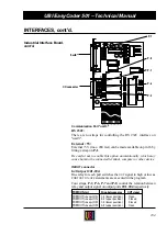
INTERFACES, cont'd.
Parallel Interface Board,
cont'd.
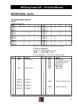
Pin
Signal
Dir.
Remarks
1
/STROBE In
2
DATA 0
In
3
DATA 1
In
4
DATA 2
In
5
DATA 3
In
6
DATA 4
In
7
DATA 5
In
8
DATA 6
In
9
DATA 7
In
10
ACK
Out
11
BUSY
Out
12
PE
Out
See note!
13
SELECT
Out
14–15
–
–
not used
16–17
GND
18
+ 5V
Out
If strap fitted on P-2. Max. 200 mA.
19–30
GND
31
/INPRM
In
32
/ERROR
Out
33–35
–
–
not used
36
/SLCTIN
In
37–38
GND
Housing
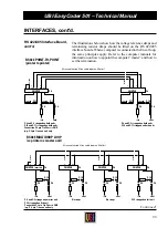
UBI offers a 3 metres (9.8 ft.) long
ready-made parallel communication
cable (36-p male Centronics – DB25
male).
Article No. 1-010001-00

