


Part # 4518632 (02/19/08)
Page 7
INSTALLATION
continued
edge of the grease filter.” We recommend that the ‘MINIMUM
DISTANCE BE 24” (610 MM) FROM THE FLUE OUTLET TO
THE BOTTOM EDGE OF THE FILTER WHEN THE APPLIANCE
CONSUMES MORE THAN 120,000 B.T.U. PER HOUR.
A strong exhaust fan will create a vacuum in the room, for an
exhaust system vent to work properly, replacement air must
enter the room in which the vent is located.
All gas burners and pilots need sufficient air to operate and
large objects should not be placed in front of this fryer which
would obstruct the air flow through the front. A minimum of
24” (610mm) should be provided at the front of the unit for
servicing and proper operation. Air for combustion enters
the unit below the cabinet at the base. Do not place anything
around the base or under the fryer.
Assembly Of Battery
All heavy duty batteries equipment is aligned and fitted at
the factory, from left to right and must be installed in this
order. There is a diagram provided with every heavy duty
battery. C836-1-35F fryers may be installed to battery with
other US Range Cuisine Series Ranges, sharing common
manifold connections.
A. All such units should be placed in their respective battery
position. Detach valve panels to prevent damage,
remove them from the area where the battery is being
assembled.
B. Level each unit (if a range, to the oven rack) by adjusting
the six inch (6”) legs, or where legs are not used, adjust
level with shims. Readjust legs, if required.
C. Connect units together by mating the unions at each
end of the manifold. (Adjoining units must have
matching unions, unless the union parts are of the
same specifications, a leak proof connection cannot be
assured.) Hand tighten unions at this point.
D. The units should be fastened at the rear by inserting 5/16”
bolts through the holes provided at the rear of the burner
box sides. Install washer and nut and hand tighten. Be
sure of proper unit alignment in the battery before final
tightening of these bolts or unions. Improper tightening
will cause “fanning” or “bowing” of batteried units.
The final tightening of the union should be accomplished
by using a suitable spanner wrench. If such a wrench
is not available, the US Range union collar has special
ridges, and a cold chisel can be driven against these
ridges to properly seat and seal the union.
E. The manifold of this unit or the manifold of which is
a part of must be equipped with a certified pressure
regulator suitable for battery application and adjustable
for an outlet pressure at the manifold as specified on the
rating place
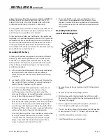
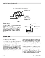
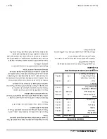
Assembly Instructions
Low Profile Backguard
~
~
1
"X"
"X"
2
5
8
7
3
6
9
4
1. Remove flue cap #6 by removing six (6) [#10] sheet metal
screws.
2. Remove front panel #5 by lifting upward.
3. With back panel #4 still attached to the left #2 and right
#3 uprights, drop uprights into the rectangular cutouts at
the rear of the range #1.
4. Fasten uprights #2 and #3 to the range #1 with four (4)
5/16” -18 bolts and flat washers #7 and #8.
5. If unit is in a battery lineup, fasten adjacent units together
at hole marked “X” with 1/4” -20 bolts, nuts, and washers.
6. Install front panel #5 previously remove.
7. Install flue cap #6 previously removed.


