41
http://www.tyan.com
4.0 Installing the Hard Drives
The following section pertains to the onboard Promise IDE controller which is the only one
that supports RAID. The other regular IDE connectors do NOT support RAID but connect
the same way.
If you wish to use your current bootable HDD (using Windows NT 4.x or 2000) as part of the
bootable mirrored (RAID 1) array, do NOT connect the hard drive yet. First, you MUST install
Windows NT 4.x or 2000 on your existing hard drive controller.
Hard drives must be of the Fast ATA-2, EIDE, or UltraDMA -33/66/100 type if you want to use
them with the RAID controller. For best performance, we recommend that you use drives of
identical model and capacity. By matching drives, you ensure compatibility as well. If you are
planning to use an UDMA -66 or 100 drive, you must use an UltraDMA -66/100 cable (Tyan has
included that cable with the motherboard).
Also, if you are planning to use striping (RAID 0), we recommend you use two new drives. For
mirroring (RAID 1), you should either use two new drives, or your old drive and a new drive (of the
same size or larger than your current drive).
Step 1:
The first step is to set the hard drive to Master, Slave, or Cable Select setting, and install
them according to the table below. Note: Sometimes the Master drive with no Slave attached is
called “single”. The Master/Slave setting differentiates two drives connected on the same cable.
NOTE: Check your HDD documentation for master, slave, and cable select settings
.
Jumper Settings (see your HDD documentation for jumper settings)
# of Drives
IDE Channel 1
IDE Channel 2
1
M
-
2
M
M
3
M & S
M
4
M & S
M & S
M=Master, S=Slave
Step 2:
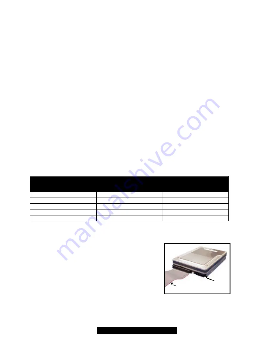
Next, you should install the drives into your
system, and connect the power. Attach one UltraDMA
cable (black connector) to each drive (if you have a Slave
drive, connect that drive to the second connector (grey
connector) on the UltraDMA cable). Make sure that Pin 1
on the cable (indicated by the colored stripe) is connected
to Pin 1 of the hard drive. See Figure I-1 (to the right) for
an example.
Figure I-1
Colored stripe
indicates Pin 1
Power
Summary of Contents for THUNDER LE-T
Page 45: ...45 http www tyan com SCSI Setup Section...
Page 46: ...46 http www tyan com...
Page 47: ...47 http www tyan com...
Page 48: ...48 http www tyan com...
Page 49: ...49 http www tyan com...
Page 50: ...50 http www tyan com...
Page 51: ...51 http www tyan com...
Page 52: ...52 http www tyan com...
Page 53: ...53 http www tyan com...
Page 54: ...54 http www tyan com...


