9
EN
CONTROL
MODULE
Symbol
Function in the master driver
Function in the slave driver
IN10
mass - not used
mass of the fire-fighting signal
IN11
input of the optical sensor 6
not used
IN12
mass - not used
not used
OUT 1-2
not used
NO feedback signal for the left direction
OUT 2-3
not used
NO feedback signal for the left direction
OUT 4-5
not used
NO feedback signal for the right direction
OUT 5-6
not used
NO feedback signal for the right direction
AUX
communication connector between master - slave controllers
communication connector between master - slave controllers
LED 1-6
connector controlling pictograms on the master side
connector controlling pictograms on the slave side
PWR
24VDC or 24VAC supply
24VDC or 24VAC supply
ENC
connector of the master module arm position encoder
connector of the slave module arm position encoder
BREAK 1-2
connector controlling the master module electromagnetic coil
connector controlling the slave module electromagnetic coil
MOTOR 1-2
connector controlling the master module engine
connector controlling the slave module engine
BEEPER 1-2
connector controlling an alarm buzzer
not used
FUSE
connector of a 5A time fuse
connector of a 5A time fuse
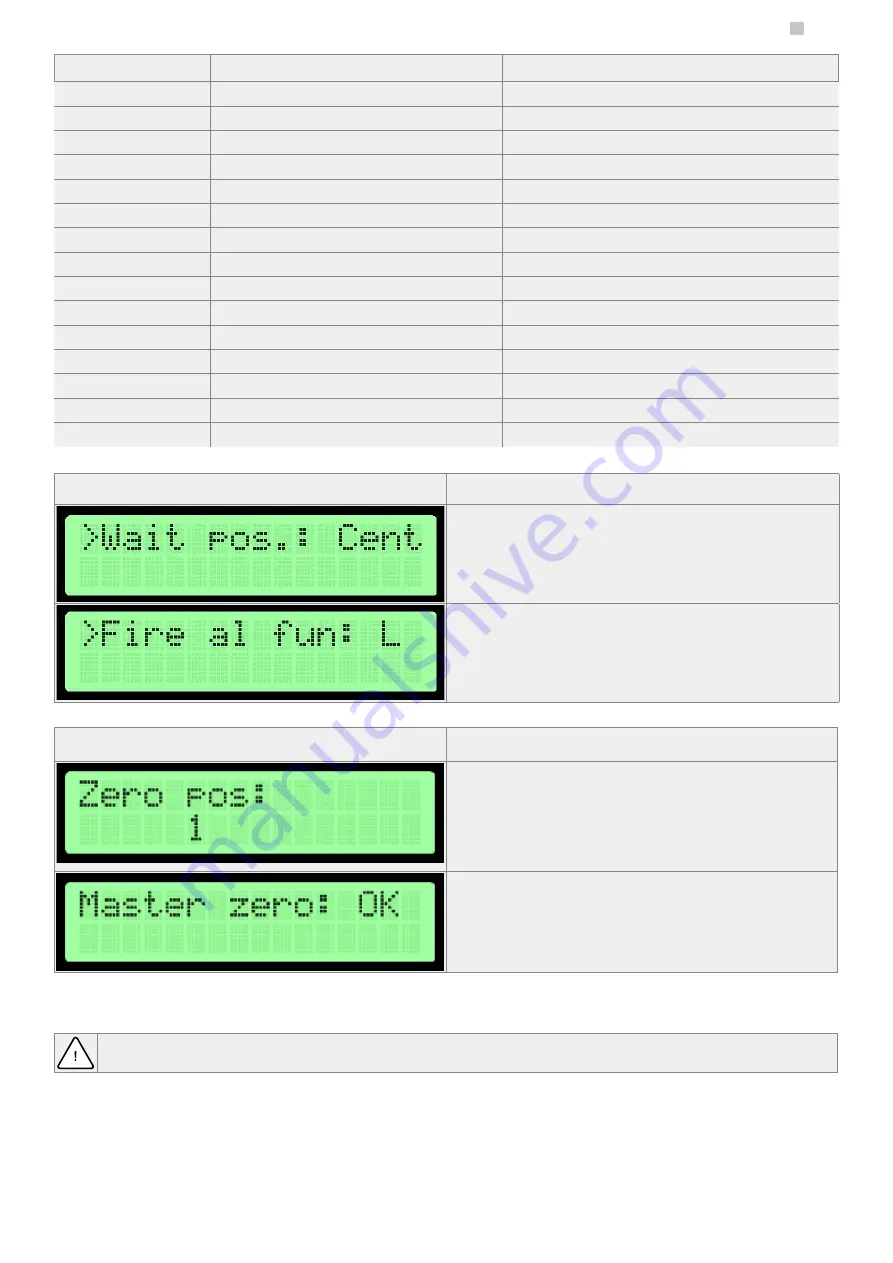
SETTINGS MENU
Arm position in a standby mode
Arm position in a standby mode (waiting for a trigger signal). If this setting is different
than the central one, it is recommended to use this setting in combination with the free
passage in that direction.
Default setting: cen
Fire alarm configuration
Set the direction in which the device opens in case of receiving a fire alarm signal.
Default setting: L
ZERO POSITION CONFIGURATION
After entering the configuration mode zero, the display shows the stage of configuration.
1.
Open position- set up arms in the open position (the side does not matter) and
confirm by pressing the encoder.
2.
Closed position- set up arms in the closed position and confirm by pressing the
encoder.
3.
Open position- set up arms in the open position opposite to that set in step 1. And
then confirm by pressing the encoder.
In the fourth step, zero positions are being validated. After pressing the encoder, you will
be moved to the settings menu.
Note: To save changes, use the Save and Exit. This only applies to the master controller.
Zero position in the slave controller is saved immediately after proper verification.
This mode is for defining an open and closed position of gate arms.
Warning: When setting the zero position the motor connector and an electromagnetic break should be disconnected from the controller. This applies to both sides
(master and slave) because their zero positions are set at the same time!
Setting the zero position takes place at the same time for the master and slave controller if communication between them is correct.


