background image

8

Modem Data Cable

Remote UPS Access

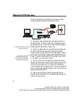
The power to the equipment connected to your UPS can be controlled
remotely  by dialing in to a phone line connected to the UPS.

(1) Make the connections to the phone line, your phone and modem (if
any) as shown above.  The LINE connector of the UPS always connects to
the incoming phone line.  The MODEM connector of the UPS connects to
telephone equipment such as phone, modem or fax.

(2) When you are ready to place your equipment in the remote mode, turn
the MODE switch (the rotary key switch) to the REMOTE position.
[Caution: the power to your equipment will be immediately removed. Make sure
you have saved all your work and were ready to shut off the system before taking
this step.]
  The amber light marked REMOTE should flash.  Leave the UPS
on.  The system is now in the REMOTE mode.

(3) When you want to turn on the equipment connected to the UPS at a
later time from another location, simply dial the number of the phone line to
which the UPS is connected.  After 3 to 5 rings, the UPS will detect the
ringing and supply power to the equipment.  Also, if the phone line becomes
busy—e.g. when a modem establishes connection—the UPS will continue to
supply the equipment with power.

(4) When you hang up the phone, the UPS will remove power to the
equipment after 30 to 40 seconds.  You can redial the number and keep the
equipment on within this time.

 The UPS will not interfere with the

modem or telephone..

¨

  It may take about a minute

after the UPS is turned on for

the first time before the MODE

switch becomes operational.

¨

U P S

O U T P U T

CAUTION

TO REDUCE THE 
RISK OF FIRE OR 
ELECTRIC SHOCK, 
INSTALL IN A 
TEMPERATURE 
AND HUMIDITY 
CONTROLLED 
AREA FREE OF 
CONDUCTIVE 
CONTAMINANTS.

WARNING

THIS UPS RECEIVES POWER FROM MORE THAN 
ONE SOURCE—DISCONNECTION OF THE AC 
SOURCE AND THE DC SOURCE IS REQUIRED TO 
DE-ENERGIZE THIS UNIT BEFORE SERVICING.
DO NOT REMOVE COVER. NO USER SERVICEABLE 
PARTS INSIDE. REFER SERVICING TO QUALIFIED 
PERSONNEL.
HAZARDOUS LIVE PARTS INSIDE THIS UPS ARE 
ENERGIZED FROM THE BATTERY SUPPLY EVEN 
WHEN THE INPUT AC POWER IS DISCONNECTED.

AC

FUSE

WARNING

FOR CONTINUED PROTECTION 
AGAINST FIRE, REPLACE ONLY WITH 
SAME TYPE AND RATING OF FUSE

AC IN

125V 7A

UNINTERRUPTIBLE
POWER  SUPPLY

AC INPUT:
UPS OUTPUT:
DC IN/OUTPUT:

SERIAL NO.

MADE IN U.S.A.

TO EXT-5000

CAUTION

TURN OFF POWER 
SWITCH DURING 
BATTERY EXTEN- 
SION CONNECTION. 
FOR DISCONNECT 
USE ONLY.  NOT
INTENDED FOR
CURRENT IN-
TERRUPTION.

MODEM

LINE

B1 B2 B3 B4

REMOTE CONTROL

BAUD
RATE

RS-232

INTERFACE

ALARM

INTERFACE

UPS-7200

120V, 60HZ, 7A MAX, P.F.=1
120V, 60HZ, 4.2A MAX, P.F.=1
24V, 30A MAX

F U

 S E   F U

 S E

     F U

  S E

5

4

3

2

1

9

8

7

6

5

4

3

2

1

9

8

7

6

ON

1

2

3

4

PC Power Cable

Phone Jack

MODEM

LINE

REMOTE CONTROL

Rear of UPS

Modem

© Copyright—2000 TSi Power Corporation.  All rights reserved.

TSi Power’s ongoing product improvement process makes specifications subject to change.

Other company’s  product names herein are for identification purposes only and may be trademarks of their respective companies.

Summary of Contents for UPS-550B

Page 1: ...POWER CORPORATION 1103 West Pierce Avenue Antigo WI 30071 USA Phone 715 623 0636 FAX 715 623 2426 Internet www tsipower com e mail sales tsipower com Copyright 2000 TSi Power Corporation All rights re...

Page 2: ...battery supply inside the UPS is 24 volts Maximum Operating Ambient Temperature for the UPS and Battery Extension Unit is 40 degrees Celsius When you are using the rack cabinet or wall mounting kits p...

Page 3: ...UPS Access 8 Typical Holdup Times 10 Trouble shooting and Maintenance 11 UPS Technical Specifications 12 Installation Procedure for Mounting Kits 13 i Copyright 2000 TSi Power Corporation All rights...

Page 4: ...the large power on off switch in the front of the UPS and turn the UPS on All your equipment hooked up to the UPS should now be ready to power up Congratulations You ve already taken a large step tow...

Page 5: ...rging Light This red light is on when battery is being charged F Inverter On Light This yellow light blinks when AC power is abnormal and UPS is operating on battery G Remote Mode Light some models Th...

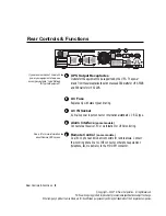
Page 6: ...odem connectors for remote access Connect the incoming phone line to LINE connector other phone equipment telephone fax modem etc to the MODEM connector U P S O U T P U T CAUTION TOREDUCETHE RISKOFFIR...

Page 7: ...uch more Its architecture is that of a standby UPS or off line UPS whose inverter is only activated when the line AC becomes irregular This has the advantage of lower cost and greater reliability sinc...

Page 8: ...e on indicating that the battery is being recharged This is normal 5 As a test you may simulate a power outage by unplugging the UPS power cord from the AC outlet All your equipment connected to the U...

Page 9: ...ours 11 When an overload occurs and the UPS shuts off you must remove the excess load and reset the UPS by turning it off and then on before the UPS will resume proper operation Your UPS will hold up...

Page 10: ...S A positive pulse 5V or higher and lasting longer than 1 4 sec will shut down the UPS when it is running on battery power Open Collector Output from UPS Normally open this transistor switch will clos...

Page 11: ...within this time The UPS will not interfere with the modem or telephone It may take about a minute after the UPS is turned on for the first time before the MODE switch becomes operational U P S O U T...

Page 12: ...ou need to access the remote PC you would dial the UPS turn on the remote PC and let your home modem and remote modem establish a connection When finished you can hang up and power to the PC will be t...

Page 13: ...y be trademarks of their respective companies Typical Holdup Times A typical desktop PC or Macintosh draws between 200 and 300 watts The table below shows some typical holdup times with a computer loa...

Page 14: ...attempt to repair the UPS High voltages are present and there are no user servicable parts inside Repairs can be performed only at the factory or at an authorized repair centers by qualified personnel...

Page 15: ...ransfer back to AC Transfer Time 1 millisecond phase locked to the AC Two long life leak proof sealed lead calcium batteries each rated at 12VDC 7A h provide 168VA h of capacity Typical recharging tim...

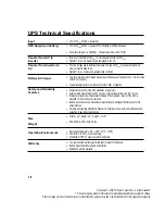
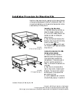
Page 16: ...ssembled properly with the equipment mounting rails securely installed at the intended location This should be either in the front or rear of the cabinet for MK 5000A or in the center of the cabinet f...

Page 17: ...he desired height Fasten the screws B provided with the kit through the mounting bracket into the rails using the clip nuts previously installed Wall Mounting for MK 5000C only 1 Make sure that the wa...

Page 18: ...IS NOT LIABLE FOR CONSEQUENTIAL DAMAGES THIS WAR RANTY GIVES YOU SPECIFIC LEGAL RIGHTS AND YOU MAY ALSO HAVE OTHER RIGHTS WHICH VARY FROM STATE TO STATE Excluding batteries Battery manufacturer s war...

Reviews: