A
A
A
A
MK-5000C
Left Br
acket
MK-5000C
Right Br
acket
C
C
C
C
MK-5000C
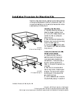
Wall Mounting Kit
16.5"
(3) Your two assistants should now hold the unit (at both ends), keeping it
in position at the desired height. Fasten the screws or bolts into the previ-
ously prepared mounting holes in the wall.
MK-5000C
Mounting Hole Locations
7"
1 4
© Copyright—2000 TSi Power Corporation. All rights reserved.
TSi Power’s ongoing product improvement process makes specifications subject to change.
Other company’s product names herein are for identification purposes only and may be trademarks of their respective companies.
the desired height. Fasten the screws
B
(provided with the kit) through
the mounting bracket into the rails using the clip nuts previously installed.
Wall Mounting (for MK-5000C only)
(1) Make sure that the wall is properly
prepared for the approximately 40lbs of
weight it would have to support. A wooden
or plywood wall should be at least 1/2” thick.
A steel wall should be at least 1/8” thick.
Mounting on plaster wall is not recom-
mended.
(2) If the wall is made of wood or plywood,
4 wood screws size #10 or larger should be
used to secure the units (
C
). If the wall is
made of steel, either 4 studs or 4 threaded
holes of size #10 or larger must be placed at
the proper location before attempting to mount the unit. The holes should
be placed 7” apart vertically, and at a horizontal distance of 16-1/2” (see
figure).

