2
GB
TKF 104 - 1
E254en1_02.doc
Proper use
The
TRUMPF TKF 104-1
bevelling machine
a
pneumatic hand machine
•
for preparation of all K-, V-, X-, and Y-shaped
welding joints with three different bevel angles
and correspondingly adjustable bevel lengths
needed for gas and electrical fusion-welding,
•
for shaping even, non-oxidizing, bare metal bevel
edges in steel and aluminium,
•
for machining chrome steel and other high-tensile
materials,
(Recommendation: model with speed control),
•
for bevelling straight and curved edges provided
that the minimum radius of concave curves is
55mm,
•
for bevelling edges on flat and bent workpieces,
particularly tubes, with an inner diameter of at
least 80mm,
•
for bevelling edges in both directions, in which
bevelling can be started and terminated anywhere
on the sheet edge,
•
for bevelling edges in normal position (carrier
under the machine) and in "upside-down position"
(carrier over the machine). This is particularly
advantageous when bevelling X- and K-shaped
welding joints.
Safety instructions
Hazardless working with this unit is only
feasible if you read the operating manual and
safety instructions (red print with the
TRUMPF identity number 125699) completely
and follow the instructions included therein.
Danger of injury
Check the unit, compressed-air tube and
reception coupling before each use.
Have all damaged parts repaired by an
expert.
Danger of injury
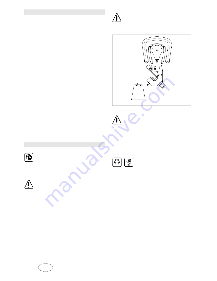
Hot chips are ejected from the chip ejector at
extremely high speeds. You should therefore
use a swarf box to collect the ejected chips.
Fig. 10977
Danger of injury
The machine is supported by the workpiece
as long as they are in contact when the
cutting arrangement is "normal" (workpiece
is horizontal). Remember that the entire
weight of the machine must be supported as
soon as it is removed from the machined
edge. (aid: suspension bracket with balancer
or retaining rope).
Always wear safety glasses, ear
protection, protective gloves and
proper footwear when working with
the machine.
•
Do not connect the compressed air unless the
machine is turned off.
•
Always disconnect the compressed-air tube from
the machine before beginning any work on the
machine!
•
Always guide the compressed-air tube back away
from the unit.
•
Use only original TRUMPF accessories.
S
S
Chip bag
Summary of Contents for TKF 104 - 1
Page 1: ...Operator s manual english TKF 104 1...
Page 2: ......


