background image

E254en1_02.doc

TKF 104 - 1

GB

3

Before initial use

1.

Read the chapter on safety.

Safety instructions

2.

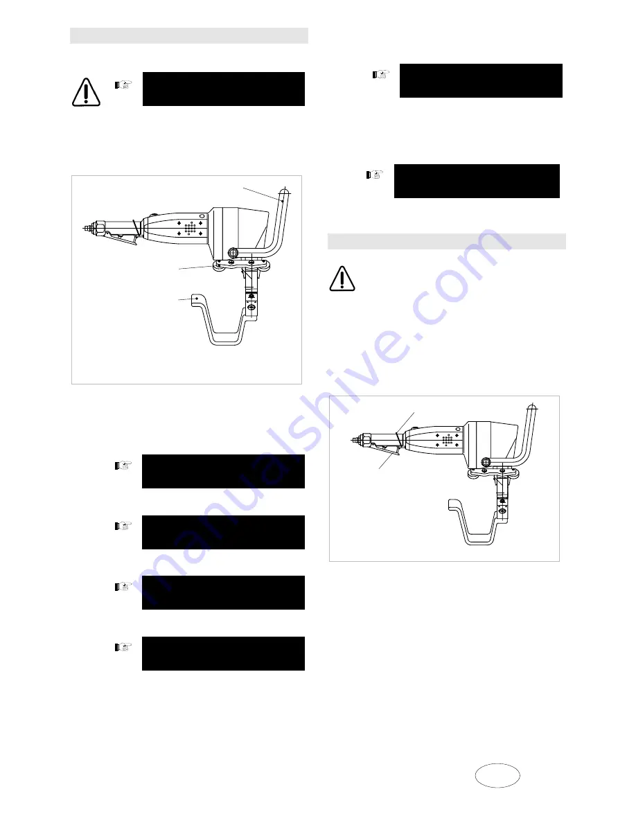
Mount the handle and the roller guide, if
necessary (these parts are provided
separately when a new machine is
delivered).

Fig. 11423

3.

Check whether the installed cutting tool is
suitable for the material that is to be
machined. Use special cutting tools for high-
tensile sheets and aluminium!

Select cutting tool

4.

Sharpen or replace blunt tools.

Sharpen cutting tool

5.

Check the bevel angle.

Bevel angle

6.

Check the bevel angle (length of bevel set).

Set length of bevel angle

7.

Adjust the machine to the sheet thickness of
the workpiece.

Sheet thickness

8.

The flow pressure of the compressed air
must be 6 bar at the point of extraction.

9.

Oil lubrication must take place for the
compressed-air motor.

Maintenance

Operating instructions

Damage to property

Check the edge of the cutting tool every hour.

Check the oil lubrication of the compressed-
air motor every hour.

Never work with blunt tools!

(the compressed-air motor may stop).

Turning the unit on and off

Fig. 11424

Turning on the unit: 

Push lever 1 forward (releases

compressed-air). Shift lever 2 (= motor ON). The
motor runs as long as the lever is pressed. Release
lever 1.

Turning off the unit: 

Release lever 2 (the lever

springs back into initial position and the flow of
compressed air is interrupted).

58

53

38

38

Handle

53

Slide handle

58

Roller guide

1

2

1

Bracket

2

Lever

Summary of Contents for TKF 104 - 1

Page 1: ...Operator s manual english TKF 104 1...

Page 2: ......

Page 3: ...e 14 3 kg Operating pressure flow pressure 6 bar Operating pressure flow pressure 6 bar Air consumption at 6 bar 3 1 m min Required inner of compressed air hose 18 mm max output not reached if is smal...

Page 4: ...s working with this unit is only feasible if you read the operating manual and safety instructions red print with the TRUMPF identity number 125699 completely and follow the instructions included ther...

Page 5: ...ickness of the workpiece Sheet thickness 8 The flow pressure of the compressed air must be 6 bar at the point of extraction 9 Oil lubrication must take place for the compressed air motor Maintenance O...

Page 6: ...e is approximately parallel to the sheet edge Press the machine against the sheet edge Sheet thickness Fig 11408 Place the machine on the sheet working position Unscrew the clamping screw 54 Adapt the...

Page 7: ...Unscrew the cutting tool 9 Fig 10981 Installing the cutting tool Fig 10981 Check the wearing plate 43 Maintenance Grease the rectangular part of the cutting tool and the bore of the supporting body li...

Page 8: ...aft 21 until the cutting tool 9 reaches its lowest point LT lower dead centre Unscrew the clamping screw 36 Turn the supporting body 52 360 as many times as necessary to reach the correct punch penetr...

Page 9: ...or mild steel order no 088503 and high tensile sheets order no 089335 has two cutting edges It must be resharpened when both edges are blunt Resharpen the cutting tool at the ends 90 on the front side...

Page 10: ...erval approx 1 operating hour Oil is refilled through the opening in the sealing screw screw plug 313 Ensure that the oil level is not too high 2 It is receommended that an oil mist lubricating device...

Page 11: ...e during regular machine mainte nance Warning Speed limiter 324 is to be handled with particular care as damage can cause overspeed See diagram in the spare parts list Changing vanes The performance o...

Page 12: ...ation Operating instructions 128640 Safety instructions red print 125699 See item in the spare parts list Options Case 121585 Suspension bracket 105001 Chip bag 116199 Punching and nibbling oil for al...

Reviews: