background image

27

S

ection

 7 — S

ervice

5. 

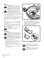
Test the blade’s balance using a blade balancer. Grind 

metal from the heavy side until it balances evenly.

NOTE: 

When replacing the blade, be sure to install the blade with 

the side of the blade marked ‘‘Bottom’’ (or with a part number 

stamped in it) facing the ground when the mower is in the 

operating position.

CAUTION: 

Use a torque wrench to tighten the 

blade spindle hex flange nut to between 70 lbs-ft 

and 90 lbs-ft.

Changing the Deck Belt

WARNING! 

Be sure to shut the engine off, remove 

ignition key, disconnect the spark plug wire(s) and 

ground against the engine to prevent unintended 

starting before removing the belt.

WARNING! 

All belts on your tractor are subject to 

wear and should be replaced if any signs of wear are 

present.

IMPORTANT: 

The V-belt found on your tractor is specially 

designed to engage and disengage safely. A substitute 

(non-

OEM)

 V-belt can be dangerous by not disengaging completely. 

For a proper working machine, use factory approved belts.

For 38” Decks

To change or replace the deck belt on your tractor, proceed as follows:
1. 

Lower the deck by moving the deck lift lever into the 

bottom notch on the right fender.

2. 

Remove the belt guards by removing the self-tapping 

screws that fasten them to the deck.

3. 

Remove the belt keeper rod from around the engine pulley.

WARNING! Avoid the possibility of a pinching 

injury. Do not place your fingers on the idler 

spring or between the belt and a pulley while 

removing the belt.

4. 

Remove the deck belt from around all pulleys, including 

the deck idler pulley.

5. 

Route the new belt as shown in Fig. 7-10.

6. 

Remount the belt guards removed earlier.

For 42” & 46” Decks

To change or replace the deck belt on your tractor, proceed as 

follows:
1. 

Remove the deck as instructed earlier in this section.

2. 

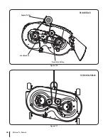
Remove the belt covers by removing the hex screws that 

fasten them to the deck. See Fig. 7-9.

3. 

It may also be necessary to loosen the hex nut on the left 

idler pulley to get the belt off the pulley and around the 

belt guard.

4. 

Carefully remove the deck belt from around the two 

spindle pulleys and the two deck idler pulleys. See Fig. 7-9.

5. 

To place the new belt, begin by routing the belt around the 

two outer spindle pulleys as shown in Fig. 7-9.

6. 

Then route the belt around the two deck idler pulleys as 

shown in Fig. 7-9.

7. 

Retighten the belt keeper rod loosened earlier.

8. 

Remount the belt guards removed earlier.

9. 

Re-install the deck, making sure the belt remains routed 

around the pulleys as instructed. See Fig. 7-11.

10.  Pull the right side of the belt, and place the narrow V side of 

the belt into the PTO pulley. 

11.  While holding the belt and pulley together, rotate the 

pulley to the left. Continue holding and rotating the pulley 

and belt until the belt is fully rolled into the PTO pulley.

Changing the Transmission Drive Belt

NOTE: 

Several components must be removed and special tools 

(i.e. air/impact wrench) in order to change the tractor’s drive belt. 

See an authorized MTD Service Dealer to have your drive belt 

replaced or phone Customer Support as instructed on page 2 for 

information on ordering a Service Manual.

Figure 7-9

Hex Washer Screws

Belt Cover

Deck Idler Pulley

Spindle Pulley

Belt Guard

Summary of Contents for 060-1878-2

Page 1: ...ractices Set Up Operation Maintenance Service Troubleshooting Warranty WARNING READ AND FOLLOW ALL SAFETY RULES AND INSTRUCTIONS IN THIS MANUAL BEFORE ATTEMPTING TO OPERATE THIS MACHINE FAILURE TO COMPLY WITH THESE INSTRUCTIONS MAY RESULT IN PERSONAL INJURY 769 09587 12 20 13 Automatic Lawn Tractor ...

Page 2: ...he time of printing Review this manual frequently to familiarize yourself with the machine its features and operation Please be aware that this Operator s Manual may cover a range of product specifications for various models Characteristics and features discussed and or illustrated in this manual may not be applicable to all models The manufacturer reserves the right to change product specificatio...

Page 3: ...movable parts Never operate this machine in bare feet or sandals 10 Be aware of the mower and attachment discharge direction and do not point it at anyone Do not operate the mower without the discharge cover or entire grass catcher in its proper place 11 Do not put hands or feet near rotating parts or under the cutting deck Contact with the blade s can amputate hands and feet 12 A missing or damag...

Page 4: ... up the slope or if you feel uneasy on it do not mow it For your safety use the slope gauge included as part of this manual to measure slopes before operating this machine on a sloped or hilly area If the slope is greater than 15 degrees as shown on the slope gauge do not operate this machine on that area or serious injury could result Do 1 Mow up and down slopes not across Exercise extreme cautio...

Page 5: ... c When practical remove gas powered equipment from the truck or trailer and refuel it on the ground If this is not possible then refuel such equipment on a trailer with a portable container rather than from a gasoline dispenser nozzle d Keep the nozzle in contact with the rim of the fuel tank or container opening at all times until fueling is complete Do not use a nozzle lock open device e Exting...

Page 6: ...Agency EPA this product has an Average Useful Life of seven 7 years or 270 hours of operation At the end of the Average Useful Life have the machine inspected annually by an authorized service dealer to ensure that all mechanical and safety systems are working properly and not worn excessively Failure to do so can result in accidents injuries or death Do not modify engine To avoid serious injury o...

Page 7: ... deck Contact with the blade s can amputate hands and feet WARNING THROWN OBJECTS This machine may pick up and throw and objects which can cause serious personal injury WARNING THROWN OBJECTS This machine may pick up and throw and objects which can cause serious personal injury BYSTANDERS Keep bystanders helpers children and pets at least 75 feet from the machine while it is in operation WARNING S...

Page 8: ...t gauge up or down until the left corner touches the slope See Figure 1 and Figure 2 5 If there is a gap below the gauge the slope is too steep for safe operation See Figure 2 above 1 5 d a s h e d l i n e Slope Gauge Figure 2 Figure 1 15 Slope 15 Slope WARNING Slopes are a major factor related to tip over and roll over accidents which can result in severe injury or death Do not operate machine on...

Page 9: ... black cable to the negative battery terminal with the bolt and hex nut See Figure 3 1 Figure 3 1 3 Position the red rubber boot over the positive battery terminal to help protect it from corrosion NOTE If the battery is put into service after the date shown on top side of battery charge the battery as instructed in the Maintenance section your Operator s Manual prior to operating the tractor Ship...

Page 10: ...eat for your tractor was not attached at the factory refer to the following steps NOTE For shipping reasons seats are either fastened to the tractor seat s pivot bracket with a plastic tie or mounted backward to the pivot bracket In either case free the seat from its shipping position and remove the adjustment knob from the bottom of seat before proceeding with the instructions below 1 As already ...

Page 11: ...nt to NOT top off your fuel tank when filling with fuel Leave an expansion area available inside the fuel tank to allow for the fuel to expand and for proper ventilation Otherwise the unit may not run properly Fill the tank in accordance with Figure 3 6 Figure 3 6 Setting the Deck Gauge Wheels Ifequipped Move the tractor on a firm and level surface preferably pavement and proceed as follows 1 Sele...

Page 12: ...t installed on the hood of your tractor at the factory refer to the steps below to install the hood scoop now 1 Remove the four screws pre installed in the hood scoop and retain for Step 2 2 Install the hood scoop onto the hood of the tractor and secure from the underside using the four screws previously removed See Figure 3 8 Figure 3 8 ...

Page 13: ... clarity Figure 4 1 Lawn Tractor controls and features are illustrated in Figure 4 1 and described on the following pages WARNING Read and follow all safety rules and instructions in this manual including the entire Operation section before attempting to operate this machine Failure to comply with all safety rules and instructions may result in personal injury Controls Features 4 13 ...

Page 14: ...Engine in the Operation section of this manual for detailed instructions regarding the Ignition Switch Module Start position Indicator Light Reverse Push Button Normal Driving Mode Stop position Reverse Caution Mode Position Figure 4 2 Shift Lever The shift lever is located on the left side of the fender and has three positions FORWARD NEUTRAL and REVERSE The tractor must not be in motion when the...

Page 15: ...rn to its original position when it s not depressed Refer to the Operation section of this manual for detailed instructions regarding the drive pedal IMPORTANT Always set the parking brake when leaving the tractor unattended Deck Lift Lever Found on your tractor s right fender the deck lift lever is used to change the height of the cutting deck To use move the lever to the left then place in the n...

Page 16: ...se extreme caution while operating the tractor in the REVERSE CAUTION MODE Always look down and behind before and while backing Do not operate the tractor when children or others are around Stop the tractor immediately if someone enters the area The REVERSE CAUTION MODE position of the key switch module allows the tractor to be operated in reverse with the blades PTO engaged IMPORTANT Mowing in re...

Page 17: ... the ON or Normal Mowing position IMPORTANT Do NOT hold the key in the START position for longer than ten seconds at a time Doing so may cause damage to your engine s electric starter 6 After the engine starts deactivate the choke control and place the throttle control in the FAST position NOTE Do NOT leave the choke control on while operating the tractor Doing so will result in a rich fuel mixtur...

Page 18: ... leaves the seat Refer to Safety Interlock Switches in the Operation section of this manual IMPORTANT The engine will automatically shut off if the PTO is engaged with the speed control lever in position for reverse travel with the ignition key in the NORMAL MOWING position Using the Deck Lift Lever To raise the cutting deck move the deck lift lever to the left then place it in the notch best suit...

Page 19: ...il drain valve then pull outward to begin draining oil After the oil has finished draining push the end of the oil drain valve back in until the tabs click into place Re cap the end of the oil drain valve to keep debris from entering the drain port Maintenance WARNING Before performing any maintenance or repairs disengage PTO move shift lever into neutral position set parking brake stop engine and...

Page 20: ...eep the rubber boot positioned over the positive terminal to prevent shorting IMPORTANT If removing the battery for any reason disconnect the NEGATIVE Black wire from it s terminal first followed by the POSITIVE Red wire When re installing the battery always connect the POSITIVE Red wire its terminal first followed by the NEGATIVE Black wire Be certain that the wires are connected to the correct t...

Page 21: ...repeat steps 4 through 11 on the opposite side of the cutting deck IMPORTANT After cleaning your deck with the Deck Wash System return to the operator s position and engage the PTO Keep the cutting deck running for a minimum of two minutes allowing the underside of the cutting deck to thoroughly dry Adjustments WARNING Never attempt to make any adjustments while the engine is running except where ...

Page 22: ...ly behind the hex cap screw just loosened clockwise up or counterclockwise down The deck is properly balanced when both blade tip measurements taken earlier are equal 5 Retighten the hex cap screw on the left deck hanger bracket when proper adjustment is achieved Seat Adjustment Refer to the Set Up and Assembly section of this manual for seat adjustment instructions Parking Brake Adjustment WARNIN...

Page 23: ...ts P P Check Spark Plug Condition Gap P P Replace Fuel Filter P NOTE This Operators Manual covers a range of product specifications for various models Characteristics and features discussed and or illustrated in this manual may not be applicable to all models The manufacturer reserves the right to change product specifications designs and equipment without notice and without incurring obligation I...

Page 24: ...ed from the top down Cutting Deck Removal NOTE Models equipped with a 38 inch deck have one deck idler pulley Models equipped with a 42 and 46 inch deck have two deck idler pulleys To remove the cutting deck proceed as follows 1 Place the PTO Blade Engage lever in the disengaged OFF position and engage the parking brake 2 Lower the deck by moving the deck lift lever into the bottom notch on the ri...

Page 25: ... 2 Connect the other end of the cable to the positive post of the jumper battery 3 Connect the second cable negative to the other post of the jumper battery 4 Make the final connection on the engine block of the tractor away from the battery Attach to a unpainted part to assure a good connection CAUTION If the jumper battery is installed on a vehicle i e car truck do NOT start the vehicle s engine...

Page 26: ...WARNING Always use a fuse with the same amperage capacity for replacement Cutting Blades WARNING Shut the engine off and remove ignition key before removing the cutting blade s for sharpening or replacement Protect your hands by using heavy gloves when grasping the blade WARNING Periodically inspect the blade and or spindle for cracks or damage especially after you ve struck a foreign object Do no...

Page 27: ...m around all pulleys including the deck idler pulley 5 Route the new belt as shown in Fig 7 10 6 Remount the belt guards removed earlier For 42 46 Decks To change or replace the deck belt on your tractor proceed as follows 1 Remove the deck as instructed earlier in this section 2 Remove the belt covers by removing the hex screws that fasten them to the deck See Fig 7 9 3 It may also be necessary t...

Page 28: ...28 Section 7 Service Figure 7 10 Deck Idler Pulley Engine Pulley Idler Bracket 38 Inch Deck Figure 7 11 42 46 Inch Deck ...

Page 29: ...ged 5 Drain fuel tank Refill with clean fresh gasoline 6 Replace air cleaner paper element or clean foam precleaner is so equipped Engine overheats 1 Engine oil level low 2 Air flow restricted 1 Fill crankcase with proper amount and weight of oil 2 Clean grass clippings and debris from around the engine s cooling fins and blower housing Engine hesitates at high RPM 1 Spark plug gap too close 1 Rem...

Page 30: ...type of ground engaging attachments e g tiller or moldboard plow Use of this type of equipment WILL void the tractor s warranty Model Number Description OEM 190 116 38 inch Deck Mulch Kit 19A30006OEM 42 inch Deck Mulch Kit 19A30005OEM 46 inch Deck Mulch Kit OEM 190 607 Deluxe Tractor Sunshade OEM 190 679 Bumper OEM 190 183 Deck Wheel Kit 38 OEM 190 180 Double Bagger Kit 38 19A30003OEM Double Bagge...

Page 31: ...n Lifetime Warranty on Polymer Snow Discharge Chute If your product is a snow thrower equipped with a polymer snow discharge chute the Snow Chute and the Snow Chute fails breaks or malfunctions the manufacturer will repair or replace the Snow Chute at no cost as long as it is still owned by the original pur chaser or the original person for whom this product was purchased as a gift Control mechani...

Page 32: ...ays If you have a question regarding your warranty coverage you should contact the MTD Consumer Group Inc Service Department In the U S A MTD LLC at P O Box 361131 Cleveland Ohio 44136 0019 or call 1 800 800 7310 or 1 330 220 4683 or log on to our Web site at www mtdproducts com In Canada MTD Products Limited Kitchener ON N2G 4J1 or call 1 800 668 1238 or log on to our Web site at www mtdcanada co...

Page 33: ...ligible for warranty coverage may be excluded from such warranty coverage if MTD Consumer Group Inc demonstrates that the outdoor equipment engine has been abused neglected or improperly maintained and that such abuse neglect or improper maintenance was the direct cause of the need for repair or replacement of the part That notwithstanding any adjustment of a component that has a factory installed...

Page 34: ... model number and serial number ready These can be found on the model plate located under the seat Refer to page 2 for more information regarding locating your model and serial numbers Component Part Number and Description 954 04060C Drive Belt Mowing Deck 42 Deck 954 04219 Drive Belt Mowing Deck 46 Deck 918 06991 Deck Spindle 42 Deck 918 06989 Deck Spindle 46 Deck 942 04308 Blade 42 Deck 942 0429...

Page 35: ...Notes 35 ...

Page 36: ...nty coverage as outlined in the warranty card and on KohlerEngines com Please review carefully as it provides you specific rights and obligations To maintain compliance with applicable emission regulations exhaust system backpressure may not exceed limits which can be found on KohlerEngines com Search by Model No select Read More then select Specs tab Record engine information to reference when or...

Page 37: ...ry Stay away while engine is in operation Keep hands feet hair and clothing away from all moving parts to prevent injury Never operate engine with covers shrouds or guards removed WARNING Accidental Starts can cause severe injury or death Disconnect and ground spark plug lead s before servicing Before working on engine or equipment disable engine as follows 1 Disconnect spark plug lead s 2 Disconn...

Page 38: ...st 1 Check oil level Add oil if low Do not overfill 2 Check fuel level Add fuel if low Check fuel system components and lines for leaks 3 Check and clean cooling areas air intake areas and external surfaces of engine particularly after storage 4 Check that air cleaner components and all shrouds equipment covers and guards are in place and securely fastened 5 Check spark arrestor if equipped F D B ...

Page 39: ...pping 1 If possible remove load by disengaging all PTO driven attachments 2 Position throttle control between half and full throttle stop engine Angle of Operation Refer to operating instructions of equipment this engine powers Do not operate this engine exceeding maximum angle of operation see specification table Engine damage could result from insufficient lubrication Engine Speed NOTE Do not ta...

Page 40: ...30 40 5W 30 10W 30 SAE 30 Check Oil Level NOTE To prevent extensive engine wear or damage never run engine with oil level below or above operating range indicator on dipstick Ensure engine is cool Clean oil fill dipstick areas of any debris 1 Remove dipstick wipe oil off 2 Reinsert dipstick into tube press completely down 3 Remove dipstick check oil level Level should be at top of indicator on dip...

Page 41: ... Co engines to maintain EPA and CARB regulatory compliance Change Oil and Filter Change oil while engine is warm 1 Clean area around oil fill cap dipstick Remove drain plug and oil fill cap dipstick Allow oil to drain completely 2 Clean area around oil filter Place a container under filter to catch any oil and remove filter Wipe off mounting surface Reinstall drain plug Torque to 125 in lb 14 N m ...

Page 42: ...ration Remove spark plug s and pour about 1 oz of engine oil into cylinder s Replace spark plug s and crank engine slowly to distribute oil 3 Disconnect negative battery cable 4 Store engine in a clean dry place Spark Plugs CAUTION Electrical Shock can cause injury Do not touch wires while engine is running Clean out spark plug recess Remove plug and replace 1 Check gap using wire feeler gauge Adj...

Page 43: ...eats High Fuel Consumption Engine Specifications Model Bore Stroke Displacement Oil Capacity Refill Spark Plug Gap Maximum Angle of Operation full oil level SV471 3 7 in 94 mm 3 4 in 86 mm 36 4 cu in 597 cc 1 6 U S qt 1 5 L 0 03 in 0 76 mm 25 SV530 SV541 SV591 SV601 Exceeding maximum angle of operation may cause engine damage from insufficient lubrication Additional specification information can b...

Page 44: ... doit être arrêté et de niveau avant d exécuter tout travail de maintenance ou d entretien La garantie s applique selon les termes précisés sur la carte de garantie et sur le site KohlerEngines com Veuillez vérifier correctement car il s agit de vos droits et obligations Enregistrez les informations concernant le moteur pour référence lors de la commande de pièces ou de demande de couverture de ga...

Page 45: ...enez vos mains pieds cheveux et vêtements à l écart de toutes les pièces mobiles pour éviter les blessures Ne faites jamais fonctionner le moteur si des couvercles des enveloppes ou des protections ont été enlevés AVERTISSEMENT Des démarrages accidentels peuvent causer des blessures graves voire mortelles Débranchez le s câble s de bougie et mettez le s à la masse avant l entretien Arrêtez le mote...

Page 46: ... Ne remplissez pas excessivement 2 Contrôlez le niveau de carburant Ajoutez du carburant si le niveau est bas Recherchez la présence de fuites sur les conduites et les composants du système d alimentation en carburant 3 Vérifiez et nettoyez les zones de refroidissement les zones d admission d air et les surfaces externes du moteur surtout après rangement 4 Assurez vous que le filtre à air et toute...

Page 47: ...e Arrêt 1 Si cela est possible retirez la charge en débranchant tous les accessoires entraînés par la prise de mouvement 2 Positionnez la commande de l accélérateur entre le demi régime et le plein régime arrêtez ensuite le moteur Angle de fonctionnement Veuillez vous reporter aux consignes d utilisation du matériel alimenté par ce moteur Ne poussez pas ce moteur au maximum de ses limites Voir le ...

Page 48: ...5W 30 10W 30 SAE 30 Contrôle du niveau d huile REMARQUE Ne faites jamais tourner le moteur si le niveau d huile est trop haut ou trop bas ceci afin d éviter toute usure ou endommagement du moteur Le moteur doit être froid Nettoyez toutes traces de débris sur les zones du bouchon de remplissage jauge 1 Dévissez la jauge essuyez la 2 Réinsérez la jauge dans le tube en l enfonçant complètement 3 Enle...

Page 49: ...té avec la réglementation EPA et CARB Remplacement du filtre et de l huile Changez l huile pendant que le moteur est encore chaud 1 Nettoyez la surface autour du bouchon de remplissage d huile et de la jauge Retirez le bouchon de vidange et le bouchon de remplissage la jauge Évacuez entièrement l huile 2 Nettoyez la surface autour du filtre à huile Placez un récipient sous le filtre pour récupérer...

Page 50: ...angez l huile pendant que le moteur est encore chaud Retirez la ou les bougies et versez environ 1 oz d huile moteur dans le ou les cylindres Retirez la ou les bougies et lancez le moteur lentement pour distribuer l huile 3 Déconnectez le câble négatif de la batterie 4 Entreposez le moteur dans un endroit propre et sec Bougies ATTENTION Les chocs électriques peuvent causer des blessures Ne touchez...

Page 51: ...chauffes Consommation trop élevée Spécifications du moteur Modèle Alésage Course Cylindrée Capacité d huile remplissage Écartement Angle d opération maximal à plein niveau d huile SV471 94 mm 3 7 po 86 mm 3 4 po 597 cm 36 4 cu po 1 5 L 1 6 pinte américaine 0 76 mm 0 03 po 25 SV530 SV541 SV591 SV601 Un angle de fonctionnement trop important peut causer des dommages du moteur liés à un manque de lub...

Page 52: ...ERTISSEMENT PRIÈRE DE LIRE TOUTES LES INSTRUCTIONS FIGURANT DANS CETTE NOTICE D UTILISATION AVANT D ESSAYER DE VOUS SERVIR DE CETTE MACHINE LE NON RESPECT DE CES INSTRUCTIONS PEUT ENTRAÎNER DES BLESSURES CORPORELLES P O Box 1386 97 KENT AVENUE KITCHENER ON N2G 4J1 Tracteur de pelouse automatique 769 09587 12 20 13 ...

Page 53: ...lisation pour vous familiariser avec la machine ses caractéristiques et son fonctionnement Sachez que cette notice peut mentionner une vaste gamme de spécifications techniques concernant différents modèles Les caractéristiques et les avantages mentionnés et ou illustrés dans cette notice peuvent ne pas s appliquer à tous les modèles Le fabricant se réserve le droit de modifier les caractéristiques...

Page 54: ... les pièces en mouvement N utilisez jamais la machine pieds nus ou en portant des sandales 10 Vérifiez la direction de la goulotte d éjection du tracteur et ne l orientez jamais vers des personnes N utilisez jamais le tracteur si le sac à herbe ou le dispositif de protection n est pas installé 11 Ne placez jamais vos mains ou vos pieds près d une pièce en mouvement ou sous le plateau de coupe Les ...

Page 55: ...nt à ces conducteurs d évaluer sérieusement leur aptitude à utiliser ce genre d équipement en toute sécurité Faites toujours preuve de bon sens dans des situations qui n ont pas été abordées dans cette notice d utilisation Adressez vous au concessionnaire agréé en cas de besoin Utilisation sur une pente Les accidents provoqués par tomber et de glisser qui se produisent souvent sur des pentes peuve...

Page 56: ... de traction et par conséquent de contrôle du tracteur sur des pentes 5 Faites toujours très attention en remorquant une machine pouvant prendre des virages serrés par ex une tondeuse Ë SBZPO EF CSBRVBHF ÏSP 1SFOF EFT WJSBHFT MBSHFT QPVS éviter de vous mettre en portefeuille 6 Avancez lentement et prévoyez une distance supplémentaire pour vous arrêter Ne passez pas au point mort pour descendre une...

Page 57: ...eures et réduire la sécurité 12 Ne modifiez pas le réglage du régulateur et ne laissez pas le moteur s emballer Le régulateur maintient le moteur à son régime maximal de fonctionnement sans danger 13 1SFOF TPJO EFT ÏUJRVFUUFT E JOTUSVDUJPOT FU SFNQMBDF MFT au besoin Respectez les règlements concernant l élimination des déchets et liquides qui risquent de nuire à la nature et à l environnement 15 B...

Page 58: ...ventilé Les gaz d échappement contiennent du monoxyde de carbone un gaz inodore et mortel 3 o 41 5 5 634 BSEF MFT TQFDUBUFVST MFT BOJNBVY EF DPNQBHOJF FU MFT FOGBOUT Ë VOF EJTUBODF E BV NPJOT QJFET EF la machine quand elle est en marche 7 35 44 5 0 µ53 Ne tondez pas sur des pentes supérieures à 15 7 35 44 5 o 463 6 Les pièces du moteur en particulier le silencieux ont tendance à chauffer pendant l...

Page 59: ...us l inclinomètre la pente est trop abrupte pour y travailler en toute sécurité Voir la Figure 2 ci dessus Pente à 15 Inclinomètre Pente à 15 UTILISEZ CET INCLINOMÈTRE POUR DÉTERMINER SI UNE PENTE EST TROP ABRUPTE POUR PERMETTRE L UTILISATION SANS DANGER DE LA MACHINE AVERTISSEMENT Les accidents provoqués par des chutes et des glissades qui surviennent souvent sur des pentes peuvent causer des ble...

Page 60: ... noir à la borne négative de la batterie avec le boulon et l écrou à six pans Voir la Fig 3 1 Figure 3 1 3 Placez la gaine en caoutchouc rouge au dessus de la borne positive de la batterie pour aider à la protéger contre la corrosion REMARQUE Si la batterie est mise en service après la date indiquée sur le dessus de la batterie chargez la selon les instructions dans la chapitre Entretien dans cett...

Page 61: ...t retirez la vis hex ou bouton sur certains modèles de la base du siège avant de continuer selon les instructions ci dessous 1 Retirez le bouton de réglage du siège installé en usine situé sous le siège Voir Figure 3 4 a 2 Alignez le siège avec le support de pivotement du siège comme illustré sur la Figure 3 4 et installez le siège sur le support du siège en insérant les deux encoches situées sous...

Page 62: ...Laissez toujours un espace pour permettre l expansion du carburant dans le réservoir et pour assurer une bonne ventilation Autrement la machine risque de ne pas fonctionner correctement Faites le plein comme à la Figure 3 6 Figure 3 6 Réglage des roues de guidage du plateau de coupe si équipée Placez le tracteur sur une surface plane et ferme de préférence goudronnée et procédez comme suit 1 Chois...

Page 63: ...e suivez les étapes ci dessous pour installer la prise d air sur le capot du tracteur 1 Retirez les quatre vis déjà installées sur la prise d air et conservez les pour l étape suivante 2 Installez la prise d air sur le capot du tracteur et fixez sa face inférieure au capot avec les quatre vis retirées antérieurement Figure 3 8 12 SECTION 2 ASSEMBLAGE MONTAGE ...

Page 64: ...ustration pour plus de clarté Commandes et caractéristiques 4 13 FT DPNNBOEFT FU DBSBDUÏSJTUJRVFT EV USBDUFVS EF QFMPVTF TPOU SFQSÏTFOUÏFT Ë MB JHVSF FU TPOU FYQMJRVÏFT EBOT MFT QBHFT suivantes AVERTISSEMENT Veuillez lire et suivre toutes les consignes de sécurité et instructions y compris le chapitre Fonctionnement au complet qui figurent dans cette notice d utilisation avant d essayer d utiliser...

Page 65: ...ur la droite du tableau de bord du tracteur et sert à régler le régime du moteur et sur certains modèles poussez à fond vers l avant le volet de départ L obturateur maintient le régime du moteur selon le réglage choisi IMPORTANT Assurez vous que la manette de commande de l obturateur se trouve à la position 3 1 MBQJO TJ WPVT DPOEVJTF MF USBDUFVS BWFD MF plateau de coupe embrayé Moving the throttle...

Page 66: ...e renseignements sur la pédale d accélérateur IMPORTANT Serrez toujours le frein de stationnement avant de laisser le tracteur sans surveillance Manette de relevage du plateau de coupe Elle se trouve sur le garde boue de droite du tracteur et sert à modifier la hauteur du plateau de coupe Déplacez la manette vers la gauche puis placez la dans l encoche correspondant à la position désirée Manette d...

Page 67: ...t le tracteur si quelqu un s approche La position REVERSE CAUTION MODE Marche arrière 1SVEFODF EV NPEVMF EV DPNNVUBUFVS E BMMVNBHF QFSNFU d utiliser le tracteur en marche arrière quand les lames prise de force sont embrayées IMPORTANT Tondre l herbe en marche arrière n est pas recommandé Pour utiliser le mode Reverse Caution Mode Marche arrière Prudence IMPORTANT F DPOEVDUFVS 0 5 PDDVQFS MF QPTUF ...

Page 68: ...ltez Mise à niveau du plateau de coupe dans le chapitre 3 4 EBOT DFUUF OPUJDF E VUJMJTBUJPO RVBOU BVY EJWFST réglages du plateau de coupe Mise en marche du moteur AVERTISSEMENT N utilisez pas le tracteur si le système de sécurité est défectueux Ce système à été conçu pour votre sécurité et protection REMARQUE POTVMUF MF DIBQJUSF 0 5 6 53 5 63 EBOT cette notice d utilisation quant aux instructions ...

Page 69: ...rité sur une pente AVERTISSEMENT Ne conduisez pas sur des pentes de plus de 15 degrés soit une élévation de 2 1 2 pieds environ par 10 pieds Le tracteur risquerait de se retourner et de vous blesser grièvement t Travaillez parallélement à la pente jamais perpendiculairement t Faites très attention en changeant de direction sur des pentes t Faites attention aux trous ornières bosses roches ou autre...

Page 70: ...le centre de MB POF EF USBWBJM 1BS MB TVJUF DIBOHF EF EJSFDUJPO QPVS évacuer l herbe coupée vers l extérieur Votre pelouse aura ainsi meilleure apparence t Ne tondez pas l herbe trop court Les mauvaises herbes pousseraient plus vite et le gazon risque de jaunir plus rapidement pendant les périodes sèches t Tondez toujours à plein régime t Si l herbe est très touffue il faudra peut être effectuer u...

Page 71: ...ice jusqu à ce que les attaches s emboîtent bien Replacez le bouchon sur la soupape pour empêcher tout débris de pénétrer dans l orifice de vidange Entretien AVERTISSEMENT Avant d effectuer tout réglage ou toute réparation débrayez la prise de force placez le sélecteur de vitesse au point mort serrez le frein de stationnement arrêtez le moteur et retirez la clé pour empêcher tout démarrage non int...

Page 72: ...uche de vaseline ou de graisse sur les bornes et sur la gaine de la borne positive t Assurez vous que la gaine est toujours bien placée sur la borne positive pour éviter tout court circuit IMPORTANT Si pour une raison quelconque il est nécessaire EF EÏNPOUFS MB CBUUFSJF EÏCSBODIF UPVKPVST MF DÉCMF 5 OPJS EF MB CPSOF OÏHBUJWF QVJT MF DÉCMF 104 5 SPVHF PST EV SFNPOUBHF EF MB CBUUFSJF CSBODIF UPVKPVS...

Page 73: ...niveau du plateau de coupe REMARQUE Vérifiez la pression des pneus du tracteur avant de SÏHMFS MF QMBUFBV EF DPVQF POTVMUF MB QBSUJF 1OFVT Ë QBHF dans cette notice d utilisation REMARQUE Consultez le chapitre Accessoires et équipement annexe pour tout renseignement concernant ceci et d autres accessoires et équipement annexe disponibles séparément pour votre tracteur Système de nettoyage Deck Wash...

Page 74: ...laires au tracteur 2 Mesurez la distance d entre l extérieur de la lame gauche et le sol et l extérieur de la lame droite et le sol Les deux relevés doivent être égaux Sinon passez au paragraphe suivant 3 Desserrez sans la retirer la vis taraudée sur le crochet de support gauche du plateau de coupe Voir la Figure 5 3 Équilibrez le plateau de coupe en utilisant une clé pour tourner le dispositif de...

Page 75: ...u filtre à huile 3 Nettoyage des bornes de la batterie 3 3 Lubrification d essieus et jantes avant 3 3 Vérification des ailettes de refroidissement du moteur 3 3 Lubrification des pivotement des pédales 3 3 Vérification des bougies et l écartement 3 3 Remplacement du filtre à carburant 3 REMARQUE Cette notice d utilisation présente les caractéristiques de plusieurs modèles Les caractéristiques men...

Page 76: ...ette de relevage du plateau dans l encoche inférieure sur le garde boue de droite 3 Dégagez la tige de retenue de la courroie B qui se trouve près de la poulie motrice en retirant la vis auto taraudeuse A qui la maintient en place Voir la Figure 7 1 REMARQUE Notez dans quel trou l autre extrémité de la courroie est enfoncée pour la remonter correctement 4 Dégagez la courroie C de la prise de force...

Page 77: ... de chaque véhicule est arrêté Faites attention que les pinces des câbles ne se touchent pas 1 Branchez le câble positif sur la borne positive de la batterie à plat du tracteur 2 Branchez l autre extrémité du câble positif sur la borne positive de la batterie d appoint 3 Branchez le câble négatif sur l autre borne de la batterie d appoint 4 Finalement branchez l autre extrémité du câble négatif su...

Page 78: ...z la clé d allumage débranchez le fil de la bougie et mettez le à la masse contre le moteur pour empêcher tout démarrage accidentel avant de démonter les lames pour les aiguiser ou les remplacer Portez toujours des gants épais ou utilisez un chiffon pour manipuler les lames AVERTISSEMENT Examinez régulièrement les fusées pour vous assurer qu ils ne sont pas fendillés ou endommagés surtout après av...

Page 79: ...rroie du plateau de coupe 1 Démontez le plateau de coupe de la façon expliquée plus tôt 2 Retirez les couvre courroies en enlevant les vis à rondelles hex qui les maintiennent sur le plateau de coupe Voir la Figure 7 9 3 Il faudra peut être desserrer l écrou à six pans qui se trouve sur la poulie de tension gauche pour pouvoir dégager la courroie de la poulie et du dispositif de protection de la c...

Page 80: ...29 Section 7 Service Figure 7 9 Poulie de tension du plateau de coupe Poulie motrice Support de poulie de tension Plateaux de coupe de 38 Figure 7 10 Plateaux de coupe de 42 po et 46 po ...

Page 81: ...évent ou remplacez le capuchon 5 Débranchez la canalisation d essence au carburateur pour vider le réservoir d essence Faites le plein avec une essence fraîche 6 Remplacez le filtre à air ou le pré nettoyeur Moteur surchauffe 1 Niveau d huile est est trop bas 2 La circulation d air est gênée 1 Faites le plein d huile du carter 2 Essuyez les brins d herbe et débris autour des ailerons refroidissant...

Page 82: ...ou charrue par ex l emploi de ce genre d accessoires rendra la garantie nulle et non avenue Numéro de modèle Description OEM 190 116 Ensemble de déchiquetage 38 po 19A30006OEM OTFNCMF EF EÏDIJRVFUBHF QP 19A30005OEM OTFNCMF EF EÏDIJRVFUBHF QP OEM 190 607 1BSF TPMFJM EF MVYF QPVS USBDUFVS OEM 190 679 1BSF DIPDT OEM 190 183 Roue de plateau de coupe 38 po OEM 190 180 Collecteur d herbe à 2 sacs pour p...

Page 83: ... dès l apparition d un QSPCMÒNF FT SÏQBSBUJPOT TPVT HBSBOUJF EFWSBJFOU ÐUSF FGGFDUVÏFT EBOT VO EÏMBJ SBJTPOOBCMF OF EÏQBTTBOU QBT KPVST 1PVS UPVUF question concernant vos droits et responsabilités en vertu de cette garantie adressez vous au Services technique de MTD Consumer SPVQ OD Aux États Unis 5 1 0 PY MFWFMBOE 0IJP PV BQQFMF MF PV MF 7PVT pouvez aussi visiter notre site web au www mtdproducts...

Page 84: ...mptée PIÈCES GARANTIES La réparation ou le remplacement de toute pièce garantie admissible à la garantie peut être exclus e de celle ci si MTD Consumer SPVQ OD QFVU QSPVWFS RVF MF NPUFVS EF M ÏRVJQFNFOU NPUPSJTÏ B GBJU M PCKFU E BCVT EF OÏHMJHFODF E VO FOUSFUJFO JODPSSFDU PV TJ cet abus cette négligence ou l entretien incorrect a été causé e de façon directe par la réparation ou le remplacement de...

Page 85: ... GJO E VOF QÏSJPEF EF DFOU WJOHU KPVST Ë DPNQUFS EF MB EBUF d achat à remplacer la batterie défectueuse à l acheteur initial pour la moitié 1 2 du prix de détail en vigueur de la batterie à la date du retour de celle ci Garantie limitée de la goulotte d éjection en polymère Si le matériel en question est une souffleuse à neige ÏRVJQÏF E VOF HPVMPUUF E ÏKFDUJPO FO QPMZNÒSF MB iHPVMPUUFw FU RVF DFMM...

Page 86: ...nées et ou représentées dans cette notice ne s appliquent pas nécessairement à tous les modèles Le fabricant se réserve le droit de modifier les caractéristiques les dessins et l équipement proprement dit sans préavis ni obligation REMARQUE Vous pouvez télécharger un livret contenant la liste complète des pièces détachées en visitant www mtdcanada ca ou FO UÏMÏQIPOBOU BV QPVS FO BDIFUFS VO 1SÏQBSF...

Page 87: ...36 Notes ...

Page 88: ... doit être arrêté et de niveau avant d exécuter tout travail de maintenance ou d entretien La garantie s applique selon les termes précisés sur la carte de garantie et sur le site KohlerEngines com Veuillez vérifier correctement car il s agit de vos droits et obligations Enregistrez les informations concernant le moteur pour référence lors de la commande de pièces ou de demande de couverture de ga...

Page 89: ...enez vos mains pieds cheveux et vêtements à l écart de toutes les pièces mobiles pour éviter les blessures Ne faites jamais fonctionner le moteur si des couvercles des enveloppes ou des protections ont été enlevés AVERTISSEMENT Des démarrages accidentels peuvent causer des blessures graves voire mortelles Débranchez le s câble s de bougie et mettez le s à la masse avant l entretien Arrêtez le mote...

Page 90: ... Ne remplissez pas excessivement 2 Contrôlez le niveau de carburant Ajoutez du carburant si le niveau est bas Recherchez la présence de fuites sur les conduites et les composants du système d alimentation en carburant 3 Vérifiez et nettoyez les zones de refroidissement les zones d admission d air et les surfaces externes du moteur surtout après rangement 4 Assurez vous que le filtre à air et toute...

Page 91: ...e Arrêt 1 Si cela est possible retirez la charge en débranchant tous les accessoires entraînés par la prise de mouvement 2 Positionnez la commande de l accélérateur entre le demi régime et le plein régime arrêtez ensuite le moteur Angle de fonctionnement Veuillez vous reporter aux consignes d utilisation du matériel alimenté par ce moteur Ne poussez pas ce moteur au maximum de ses limites Voir le ...

Page 92: ...5W 30 10W 30 SAE 30 Contrôle du niveau d huile REMARQUE Ne faites jamais tourner le moteur si le niveau d huile est trop haut ou trop bas ceci afin d éviter toute usure ou endommagement du moteur Le moteur doit être froid Nettoyez toutes traces de débris sur les zones du bouchon de remplissage jauge 1 Dévissez la jauge essuyez la 2 Réinsérez la jauge dans le tube en l enfonçant complètement 3 Enle...

Page 93: ...té avec la réglementation EPA et CARB Remplacement du filtre et de l huile Changez l huile pendant que le moteur est encore chaud 1 Nettoyez la surface autour du bouchon de remplissage d huile et de la jauge Retirez le bouchon de vidange et le bouchon de remplissage la jauge Évacuez entièrement l huile 2 Nettoyez la surface autour du filtre à huile Placez un récipient sous le filtre pour récupérer...

Page 94: ...angez l huile pendant que le moteur est encore chaud Retirez la ou les bougies et versez environ 1 oz d huile moteur dans le ou les cylindres Retirez la ou les bougies et lancez le moteur lentement pour distribuer l huile 3 Déconnectez le câble négatif de la batterie 4 Entreposez le moteur dans un endroit propre et sec Bougies ATTENTION Les chocs électriques peuvent causer des blessures Ne touchez...

Page 95: ...chauffes Consommation trop élevée Spécifications du moteur Modèle Alésage Course Cylindrée Capacité d huile remplissage Écartement Angle d opération maximal à plein niveau d huile SV471 94 mm 3 7 po 86 mm 3 4 po 597 cm 36 4 cu po 1 5 L 1 6 pinte américaine 0 76 mm 0 03 po 25 SV530 SV541 SV591 SV601 Un angle de fonctionnement trop important peut causer des dommages du moteur liés à un manque de lub...

Reviews: