background image

30

EN

electric heater TEH 200 / TEH 300 / TEH 400

List of spare parts

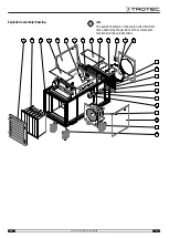
Spare parts

TEH 200

TEH 300

TEH 400

Item

Designation

Quantity Trotec no.

Trotec no.

Trotec no.

1

Main switch

1

P 1000 1454

P 1000 1454

P 1000 1532

2

Heating elements

6 x P 1000 1905

12 x P 1000 1905

18 x P 1000 1905

3

LED element white 24 V

2

P 1000 1447

P 1000 1447

P 1000 1447

4

LED element green 24 V

1

P 1000 1445

P 1000 1445

P 1000 1445

5

LED element red 24 V

1

P 1000 1446

P 1000 1446

P 1000 1446

6

Indicator light yellow

1

P 1000 1450

P 1000 1450

P 1000 1450

7

Indicator light green

1

P 1000 0244

P 1000 0244

P 1000 0244

8

Indicator light red

1

P 1000 1448

P 1000 1448

P 1000 1448

9

Indicator light white

1

P 1000 1449

P 1000 1449

P 1000 1449

10

Air filter

1

P 1000 1563

P 1000 1563

1 x P 1000 1563
1 x P 1000 1564

11

Cam switch

1

P 1000 1455

P 1000 1455

P 1000 1455

12

Trestle roller

2

P 1000 1394

P 1000 1394

P 1000 1394

13

Lockable swivel castor

2

P 1000 1393

P 1000 1393

P 1000 1393

14

Push button green

1

P 1000 1443

P 1000 1443

P 1000 1443

15

Push button red

1

P 1000 1444

P 1000 1444

P 1000 1444

16

Control cabinet filter TEH

1

P 1000 1392

P 1000 1392

P 1000 1392

17

Radial fan

1

P 1000 1383

P 1000 1994

P 1000 1384

18

Relay

2

P 1000 6608

P 1000 6608

P 1000 6608

19

Operating hours counter

1

P 1000 1477

P 1000 1477

P 1000 1477

20

Lateral insulation
Base insulation

2 x P 1000 1989
2 x P 1000 1509

2 x P 1000 1989
2 x P 1000 1509

2 x P 1000 1512
2 x P 1000 1511

21

Pressure sensor

1

P 1000 1388

P 1000 1388

P 1000 1388

22

Semi-conductor relay

4 x P 1000 1431

8 x P 1000 1431

12 x P 1000 1431

23

Load relay 24 V

4 x P 1000 1238

8 x P 1000 1238

12 x P 1000 1238

24

Power adapter

1

P 1000 1313

P 1000 1313

P 1000 1313

25

Safety temperature limiter

1

P 1000 1432

P 1000 1432

P 1000 1432

26

Fuse C 10 A

1

P 1000 4058

P 1000 4058

P 1000 4058

27

Fuse C 16 A

1

P 1000 4057

P 1000 4057

P 1000 4057

28

Fuse B 32 A

2 x P 1000 4056

4 x P 1000 4056

6 x P 1000 4056

29

Temperature probe

1

P 1000 1430

P 1000 1430

P 1000 1430

30

Temperature probe

1

P 1000 1429

P 1000 1429

P 1000 1429

31

Isolating terminal

1

P 1000 1561

P 1000 1561

P 1000 1561

32

Protective frame (incl. mounting brackets)

1

P 1000 6972

P 1000 6972

P 1000 6973

33

Air filter inspection door

1

P 1000 6974

P 1000 6974

P 1000 6975

34

Fan cover

2

P 1000 6976

P 1000 6976

P 1000 6977

35

Control cabinet cover

1

P 1000 6978

P 1000 6978

P 1000 6979

36

E-heater cover

1

P 1000 6980

P 1000 6980

P 1000 6981

37

Spigot

1

P 1000 1386

P 1000 1386

P 1000 1387

38

Cover

2

P 1000 1982

P 1000 1982

P 1000 1983

Summary of Contents for TEH 200

Page 1: ...TRT BA TEH200 TEH300 TEH400 TC2014 33 003 EN TEH 200 TEH 300 TEH 400 EN ORIGINAL INSTRUCTIONS ELECTRIC HEATER ...

Page 2: ...at the instructions must be observed You can download the current version of the instructions and the EU declaration of conformity via the following link TEH 200 https hub trotec com id 42896 TEH 300 https hub trotec com id 42897 TEH 400 https hub trotec com id 42898 Safety Read this manual carefully before starting or using the device Always store the manual in the immediate vicinity of the devic...

Page 3: ...modifications or alterations to the device are forbidden Personnel qualifications People who use this device must be aware of the dangers that occur when working with electric heaters have read and understood the instructions especially the Safety chapter Electrically skilled person Electrically skilled personnel must be able to read and understand electric circuit diagrams to put electrical syste...

Page 4: ...nd powder coated The device is designed ready to install and comes with all the electrical and mechanical components as well as safety installations required for safe and functional operation To ensure safe transport and operation the device is also equipped with a shock protection frame Functioning principle The air is taken in by the fan via the integrated bag filter 10 and heated by means of th...

Page 5: ...he responsible dealer or manufacturer where the purchase was made The electric heater may only be lifted at the points provided with lifting gear forklift pockets 6 transport lugs 2 intended for handling The carrying capacity of the lifting gear must be suitable for the weight of the electric heater see technical data 2 5 6 7 To make the device easier to transport it is fitted with wheels Only whe...

Page 6: ...an be stacked for storage purposes In doing so observe the following Only use suitable lifting gear Make sure that the rollers of the device at the bottom are locked and the device cannot move To protect the rollers and the frame the bottommost device is to be jacked up as illustrated below Warning To prevent damage to the device the bottom strut should not be allowed to rest on the support A mini...

Page 7: ...o minimize the risk Inserting the air filter Note Do not operate the device without an inserted air filter Without the air filter the inside of the device will be heavily contaminated This could reduce the performance and result in damage to the device Make sure that the air filter is installed before switching the device on Connecting the power cable Insert the mains plug into a properly secured ...

Page 8: ... and maximum temperature increase T approx 60 C 4 Actuate the green EIN ON button 14 ð The green BETRIEB OPERATION lamp 16 will be illuminated while the BEREIT STAND BY lamp 17 goes out ð The electric heater starts up in the selected temperature level Note The air outlet temperature is electronically limited to approx 60 C 5 C regardless of the preselection In case of the standard models the level...

Page 9: ...lectrical control box 12 12 Overtemperature protection For overheating protection the electric heater comes equipped with several safety elements Disconnection of the electric heating from the mains when falling below the minimum air volume Reduction of the maximum air outlet temperature at approx 65 C Rundown operation of the fan after switch off to dissipate the accumulated heat at the electric ...

Page 10: ...the menu 26 21 22 23 The following parameters can be called up Volumetric flow in m3 h airflow Input temperature in C temp in Output temperature in C temp out Output temperature in C delta T Digital operating hours display in h run hours Errors and faults The device has been checked for proper functioning several times during production If malfunctions occur nonetheless check the device according ...

Page 11: ...immediately If no warmth is required set the selection step switch to position 0 Electric installation One or several electrical components may have failed Have the electric installation checked and if required defective parts replaced by a qualified electrician Pressure sensor tripped The minimum air volume was not reached See fault Insufficient air flow rate Faults control unit For reading the f...

Page 12: ... mains plug while pulling the power cable out of the mains socket Warning of electrical voltage Maintenance tasks and repair work may only be performed by qualified electricians or Trotec Cleaning the housing Clean the housing with a soft damp and lint free cloth Ensure that no moisture enters the housing Protect electrical components from moisture Do not use any aggressive cleaning agents such as...

Page 13: ...y Check air inlets and outlets for dirt and foreign objects and clean if necessary X Cleaning the exterior X X Visual inspection of the inside of the device for dirt X X Checking of air inlet grid and air filter for dirt and foreign objects and cleaning or replacement if necessary X X Air filter replacement X Checking for damage X Checking the safety temperature limiter X Check the attachment scre...

Page 14: ... Date Signature 7 Date Signature 8 Date Signature 9 Date Signature 10 Date Signature 11 Date Signature 12 Date Signature 13 Date Signature 14 Date Signature 15 Date Signature 16 Date Signature Technical annex Technical data Parameter Value Model version 3 0 TEH 200 TEH 300 TEH 400 Article number 1 410 000 150 1 410 000 155 1 410 000 160 Max amount of air 3 000 m3 h 6 000 m3 h 9 000 m3 h Heating ca...

Page 15: ...60 Hz 3 PE 400 V 50 60 Hz 3 PE 400 V 50 60 Hz Max current consumption 61 A 41 5 kW 123 A 84 kW 182 A 125 5 kW Fusing mains connection 63 A CEE 63 A 5 pin 125 A CEE 125 A 5 pin 200 A termination Sound pressure level 3 m distance 75 dB A 76 dB A 78 dB A Hose connector Ø 450 mm Ø 450 mm Ø 600 mm Suitable for hose lengths to 100 m 100 m 100 m Mobility wheeled forklift crane wheeled forklift crane whee...

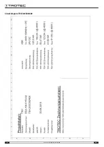
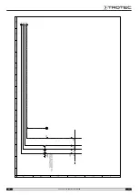
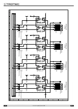
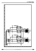
Page 16: ...16 EN electric heater TEH 200 TEH 300 TEH 400 Circuit diagram TEH 200 300 400 ...

Page 17: ...EN 17 electric heater TEH 200 TEH 300 TEH 400 ...

Page 18: ...18 EN electric heater TEH 200 TEH 300 TEH 400 ...

Page 19: ...EN 19 electric heater TEH 200 TEH 300 TEH 400 ...

Page 20: ...20 EN electric heater TEH 200 TEH 300 TEH 400 ...

Page 21: ...EN 21 electric heater TEH 200 TEH 300 TEH 400 ...

Page 22: ...22 EN electric heater TEH 200 TEH 300 TEH 400 ...

Page 23: ...EN 23 electric heater TEH 200 TEH 300 TEH 400 ...

Page 24: ...24 EN electric heater TEH 200 TEH 300 TEH 400 ...

Page 25: ...EN 25 electric heater TEH 200 TEH 300 TEH 400 ...

Page 26: ...26 EN electric heater TEH 200 TEH 300 TEH 400 ...

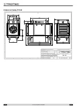
Page 27: ...express authority Offenders are liable to the payment of damages Weitergabe sowie Vervielfältigung dieser Unterlage Verwertung und Mittteilung ihres Inhalts ist nicht gestattet soweit nicht ausdrücklich zugestanden Zuwiderhandlungen verpflichten zu Schadenersatz Projekt Norm DIN Pos Nr Grebbener Straße 7 D 52525 Heinsberg DIN ISO 2768 1m Stückzahl 2 Allgem Toleranz 1 10 TEH 200 300 3 0 Z HH 200u 3...

Page 28: ...ut express authority Offenders are liable to the payment of damages Weitergabe sowie Vervielfältigung dieser Unterlage Verwertung und Mittteilung ihres Inhalts ist nicht gestattet soweit nicht ausdrücklich zugestanden Zuwiderhandlungen verpflichten zu Schadenersatz Projekt Norm DIN Pos Nr Grebbener Straße 7 D 52525 Heinsberg DIN ISO 2768 1m Stückzahl 3 Allgem Toleranz 1 10 TEH 400 Z HH 200u 300 Ko...

Page 29: ... TEH 400 Exploded assembly drawing Info The position numbers of the spare parts differ from those describing the positions of the components mentioned in these instructions 4 3 5 1 11 15 16 8 6 9 7 14 17 13 12 10 2 37 36 35 34 33 32 38 38 ...

Page 30: ...1000 1383 P 1000 1994 P 1000 1384 18 Relay 2 P 1000 6608 P 1000 6608 P 1000 6608 19 Operating hours counter 1 P 1000 1477 P 1000 1477 P 1000 1477 20 Lateral insulation Base insulation 2 x P 1000 1989 2 x P 1000 1509 2 x P 1000 1989 2 x P 1000 1509 2 x P 1000 1512 2 x P 1000 1511 21 Pressure sensor 1 P 1000 1388 P 1000 1388 P 1000 1388 22 Semi conductor relay 4 x P 1000 1431 8 x P 1000 1431 12 x P ...

Page 31: ...electronic equipment in your vicinity The addresses can be obtained from your municipality or local administration For further return options provided by us please refer to our website www trotec24 com The separate collection of waste electrical and electronic equipment aims to enable the re use recycling and other forms of recovery of waste equipment as well as to prevent negative effects for the...

Page 32: ...Trotec GmbH Co KG Grebbener Str 7 D 52525 Heinsberg 49 2452 962 400 49 2452 962 200 info trotec com www trotec com ...

Reviews: