4
EN
electric heater TEH 200 / TEH 300 / TEH 400
Warning
In order to avoid overheating and fire hazards, the
heater must not be covered.
Behaviour in the event of an emergency
1. Immediately switch the device off via the main emergency
stop switch or the emergency stop at the upstream
distributor.
2. Remove persons from the danger area.
3. Disconnect the device from the electric circuit.
4. Do not reconnect a defective device to the mains.
Information about the device
Device description
The electric heater was designed as a robust, mobile unit also
to be positioned outdoors.
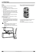
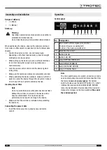
The device comes equipped with two lockable swivel castors (5)
and two trestle rollers (7) each. Forklift pockets and crane lugs
are attached to the housing as transport aids, enabling
convenient transport and space-saving storage by stacking up
to 3 devices on top of each other.
The housing is designed as welded frame construction and
provided with partially removable steel sheet panels. The
electrical control box made of steel is mounted in horizontal
position, protected between the stacking handle bars on the
housing, and contains all switching devices, operating
elements, indicator lights, safety devices and the control unit.
All steel and sheet metal parts are galvanized and powder-
coated.
The device is designed ready-to-install and comes with all the
electrical and mechanical components as well as safety
installations required for safe and functional operation.
To ensure safe transport and operation, the device is also
equipped with a shock protection frame.
Functioning principle
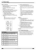
The air is taken in by the fan via the integrated bag filter (10)
and heated by means of the multi-stage electric heating. Four
different temperature levels can be selected between 0 and
100 %. These are kept constant by the integrated controller
with the maximum outlet temperature being reduced to approx.
60 °C (±5 °C).
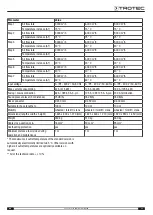
Thanks to the two-stage fan operation a higher temperature
increase can be achieved by selecting the lower stage (approx.
2/3 of the nominal air volume). The integrated, electronically
controlled control unit with air volume flow measurement and
automatic rotational speed control of the fan ensures nearly
constant volumetric flow rates covering a wide load range (e.g.
for variable hose lengths).
The temperature increase refers to the sucked in air
temperature (usually the ambient temperature) and is increased
according to the preselection. The temperature sensors at air
inlet and outlet transmit the current temperature values to the
control unit, which then, depending on the demand, keeps the
preselected temperature increase constant by means of the
control and operation of individual heating elements or the
entire heater.
Summary of Contents for TEH 200
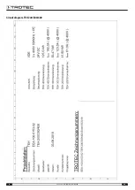
Page 16: ...16 EN electric heater TEH 200 TEH 300 TEH 400 Circuit diagram TEH 200 300 400 ...
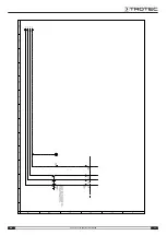
Page 17: ...EN 17 electric heater TEH 200 TEH 300 TEH 400 ...
Page 18: ...18 EN electric heater TEH 200 TEH 300 TEH 400 ...
Page 19: ...EN 19 electric heater TEH 200 TEH 300 TEH 400 ...
Page 20: ...20 EN electric heater TEH 200 TEH 300 TEH 400 ...
Page 21: ...EN 21 electric heater TEH 200 TEH 300 TEH 400 ...
Page 22: ...22 EN electric heater TEH 200 TEH 300 TEH 400 ...
Page 23: ...EN 23 electric heater TEH 200 TEH 300 TEH 400 ...
Page 24: ...24 EN electric heater TEH 200 TEH 300 TEH 400 ...
Page 25: ...EN 25 electric heater TEH 200 TEH 300 TEH 400 ...
Page 26: ...26 EN electric heater TEH 200 TEH 300 TEH 400 ...


