background image

________________________________ ________________________________ ___________  

NORMAL.DOT 

Gespeichert in:G:\Support\Dokumentationen_CDs\8003Speedy\Service Manual\Servicemanual 8003.doc 

Gespeichert  am:2003/03/10  

max 


Version 14 


Seite 16 von 87 

I N D I V I D U A L  M A R K I N G  S Y S T E M S 


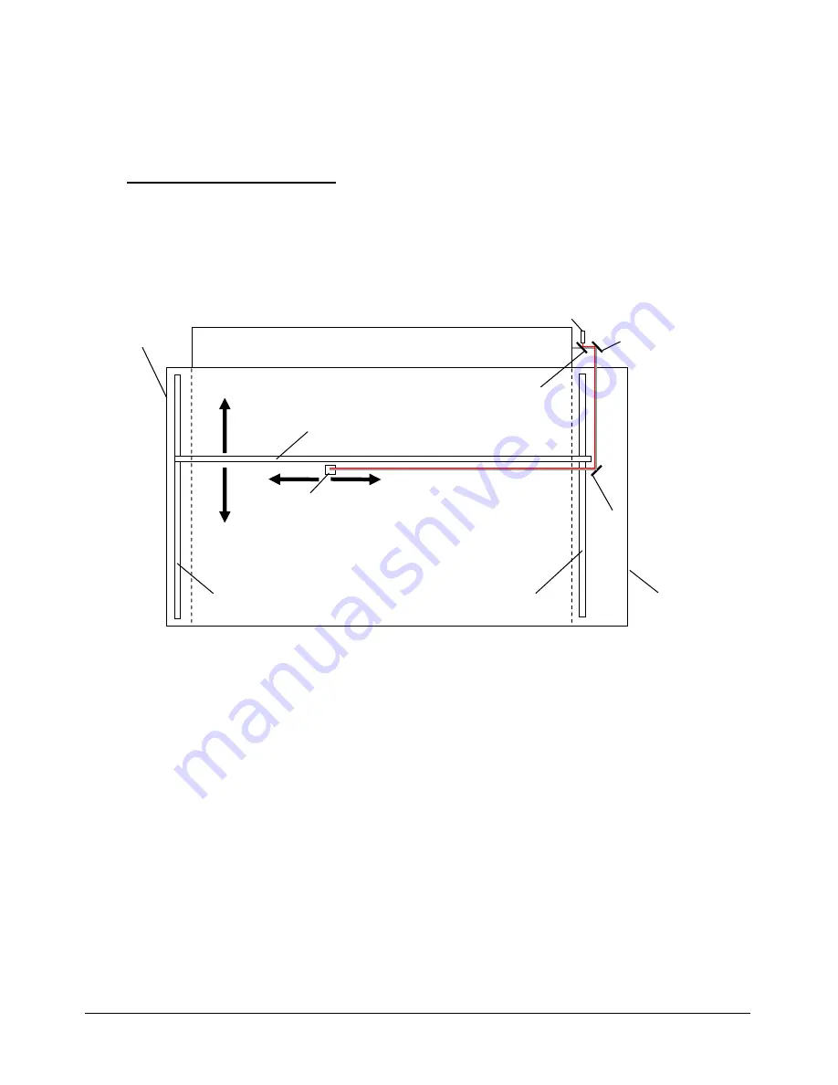
Beam path of the Speedy: 


CO

2

 Laser Tube 

Mirror No 2 

Mirror No 3 

Mirror No 1 

Beam coupler 

Aiming Laser diode 

Beam path of the Speedy model 

X-Axis 

Left Y-Axis 

Right  Y-Axis 

Maintenance 
panel 

Service access 
panel 

Summary of Contents for Speedy C100

Page 1: ...03 10 max Version 14 Seite 1 von 87 INDIVIDUAL M ARKING SYSTEMS SERVICE MANUAL 8003 Trotec Speedy C12 8003 Trotec Speedy C25 8003 Trotec Speedy C50 8003 Trotec Speedy C100 Trotec Produktions u Vertriebs GmbH Linzer Straße 156 A 4600 Wels Tel 43 7242 239 0 Fax 43 7242 239 7380 E Mail TROTEC trodat net Version 1 1 January 1999 ...

Page 2: ...ny other purpose without the written permission of Trotec Wels Notice Trotec Wels does not assume any liability arising out of the application or use of any products curcuits or software described herein Neither does it convey a license under it s patent rights nor the patent rights of others Trotec Wels further reserves the right to make any changes in any products described herein without notice...

Page 3: ...ng the laser tube 22 Measuring the laser power 23 Laser tube replacement 12W and 25W 25 Laser tube replacement 50W and 100W 26 6 Adjusting the Software 28 Adjusting the tickle power 28 Adjusting the Power Correction factor CL 30 Adjusting the Offset parameters 31 Overtook adjustment 33 Tab correction in the service setup 34 Tab acceleration in the service setup 35 7 Adjusting the Hardware 36 Ruler...

Page 4: ...ent components 66 14 Firmware Update 67 Steps for updating the firmware 67 15 Network installation of Trotec laser engravers 69 16 Software tips tricks 72 Rastering images in Corel Draw 72 How to produce a Seal Press 73 17 Marking metals using metal mark paint 74 18 Speedy error codes 75 Software feedback 75 Hardware feedback 78 19 FAQ s 80 20 Recommended service intervals 83 Warranty Regulations ...

Page 5: ...in G Support Dokumentationen_CDs 8003Speedy Service Manual Servicemanual 8003 doc Gespeichert am 2003 03 10 max Version 14 Seite 5 von 87 INDIVIDUAL M ARKING SYSTEMS 1 Main components of the Speedy laser engraver 14 16 18 15 ...

Page 6: ...eite 6 von 87 INDIVIDUAL M ARKING SYSTEMS 1 service socket 15 Power supply 2 autofocus sensor 10 X axis 3 focussing head 11 keypad 4 engraving table 12 front lid 5 Y axis connector 13 power socket 6 Polycarbonate door 14 service access panel 7 Laser tube cover 16 right interlock front lid 8 Exhaust connector 18 maintenance panel 9 Product ID label ...

Page 7: ... electricity ì mechanical dangers General Safety Instructions When working with the laser engraver please take note of the following safety instructions 1 Operation and service of the Speedy may only be performed by trained personnel 2 Direct exposure of skin or eyes to laser radiation may cause severe injuries The correct operation and service according to the manual can prevent hazards Operators...

Page 8: ...hese fumes It is emphasized that it is the user s responsibility to obey the national and regional threshold values for dusts fumes and gases The maximum concentration of harmful substances must not be exceeded Never use the laser engraver without an exhaust unit with appropriate filters for the treated material as cutting or engraving certain materials can produce vapours Materials causing toxic ...

Page 9: ...assification for lasers are as follows Class I laser product No known biological hazard The light is shielded from any possible viewing by a person and the laser system is interlocked to prevent the laser from being on when exposed large laser printers such as the DEC LPS 40 has a 10mW HeNe driving it which is a Class IIIb laser but the printer is interlocked so as to prevent any contact with the ...

Page 10: ...r locks to prevent the system from being used with the protective covers off Emission indicators to show that the laser is in use Mechanical shutters to block the beam Red DANGER labels and aperature labels affixed to the laser The reflected beam should be considered as dangerous as the primary beam again I have seen a 1 000 watt CO2 laser blast a hole through a piece of steel so imagine what it w...

Page 11: ...ure CAUTION Technicians who are performing service procedures must be trained in laser safety and if they are defeating interlocks they must wear laser protective eyewear designed for the 10 6µm CO2 laser energy The top door front door and the maintenance access panel are interlocked If the interlocks are defeated access to laser class IV radiation is possible through any of these doors All other ...

Page 12: ...nger to get in contact with parts under high voltage Therefore it is absolutely necessary that service and repair work is only done while the power supply is unplugged In any case all safety laws and standards in connection with electricity must be obeyed IMPORTANT REMARK Usually you do not need to get in touch with the electrical and electronic components In case you do that when servicing or rep...

Page 13: ...flashing which indicates that the machine now is in service mode In this case the machine represents a laser class IV 4 product and special safety provisions are necessary emission indicator Audible Warning When starting up the laser engraver without closing the cover there is an intermittent beep This indicates that the interlock system has not been checked yet You can run the machine only if all...

Page 14: ...le before and after opening a cover Labels with the name of the manufacturer date of production description of the product model number serial number and safety labels are placed on the outer side of the apparatus All these labels are mounted when producing the laser engraver These labels must not be removed If the labels are lost or damaged please contact Trotec Replacements will be sent to you f...

Page 15: ...ice technichians that have been trained by Trotec and are familiar with the hazards from lasers CAUTION Never expose any part of your body to the beam as this could result in serious injuries CAUTION To do the alignment it is absolutely necessary to wear laser protection glasses What you have to know The number of the mirrors is counted from the outlet of the laser tube to the engraving head from ...

Page 16: ...3Speedy Service Manual Servicemanual 8003 doc Gespeichert am 2003 03 10 max Version 14 Seite 16 von 87 INDIVIDUAL MARKING SYSTEMS Beam path of the Speedy CO2 Laser Tube Mirror No 2 Mirror No 3 Mirror No 1 Beam coupler Aiming Laser diode Beam path of the Speedy model X Axis Left Y Axis Right Y Axis Maintenance panel Service access panel ...

Page 17: ...ING SYSTEMS What you have to do 1 Disassemble the cover on the right side of the machine 10mm allen key 2 Take your laser protection glasses and remove the grey cover of the first mirror at the rear of your laser right side wearing the sign DANGER INVISIBLE LASER RADIATION WHEN OPEN AVOID EYE OR SKIN EXPOSURE TO DIRECT OR SCATTERED RADIATION 3 Remove mirrors 2 and 3 Removal of mirror 2 Removal of ...

Page 18: ...r 2 alignment of mirror no 1 5 Move the x axis to the top position 6 Press the test button keep it pressed and then press the service button until you see a little mark on the adhesive tape This is only possible if all doors are closed or a service plug is put into the socket The mark should be in the centre of the hole If you don t see a mark adjust the two brass screws at mirror 1 until you can ...

Page 19: ... masking tape on the hole in front of mirror 3 checking the beam position at mirror 3 13 Move the engraving head to the top right corner 14 Again press the test button keep it pressed and then press the service button until you see a little mark on the adhesive tape 15 Move the engraving head to the top left corner and adjust the two brass screws at mirror 2 until you hit the spot created in step ...

Page 20: ...esive tape What you have to know The alignment is done while your machine is running To make sure the system works at a suitable power level switch your machine of and on again The laser beam is invisible To make it visible you use adhesive tape It is burned at the spot where it is hit by the laser beam and shows so a mark The tolerable displacement distance from burned dot to the centre is one si...

Page 21: ...g the test button keeping it pressed and pressing at the same time the service button until you can see a small spot on the paper tape 4 Adjust the three small screws see attached picture close to the laser pointer until the red dot hits exactly the burned spot on the paper tape 5 Check the beam position on all four corners of the engraving table You can get the highest sensitivity to changes of t...

Page 22: ... the 50W The control signal is a 5V TTL signal that comes from the main board if there is a signal Synrad tubes will indicate this with an illuminated red LED Additionally on the 100W machines the coolant velocity must be above 5 7 l min All tubes have an integrated overtemperature protection If the tube exceeds a certain limit it is switched off to prevent a damage of the gas electronics The foll...

Page 23: ...power CAUTION To make sure that there is no laser emission out of a controlled area establish a limited access area by using non flamable beam blocking curtains temporary walls or other enclosures CAUTION The laser power measurement may only be performed by service technichians that have been trained by Trotec and are familiar with the hazards from lasers CAUTION Never expose any part of your body...

Page 24: ...efeat tool into the socket on the left side of the engraving area Remove the lens Put the power meter with the black absorbing area in one of the corners of the engraving table Move the table to a height level so that the distance between engraving head and target area is approximately four centimetres setup for measuring the laser power Press the reset button on the power meter and fire the testp...

Page 25: ...average laser power Otherwise something is wrong with the beam alignment In this case measure the power directly at the beam aperture Laser tube replacement 12W and 25W 1 Switch off the Speedy and open the service acces panel using a 10 mm allen key Remove also the cover of the electronic compartment 2 Unplug the power connector black red for the lasertube on the main board connectors on the power...

Page 26: ...new tube in the reverse way 10 After the replacement you ve to do the beam alignment Laser tube replacement 50W and 100W 1 Switch off the Speedy and open the service acces panel using a 10 mm allen key Remove also the cover of the electronic compartment 2 Unplug the power connector black red for the lasertube on the main board 3 Remove the tube enclosure 4 Disconnect the six push fit fittings that...

Page 27: ...rsion 14 Seite 27 von 87 INDIVIDUAL M ARKING SYSTEMS side of the tube and remove the six philips screws on the left side before you can do that remove the cover of mirror unit 1 8 Remove the tube 9 Assemble the new tube in the reverse way 10 After the replacement you ve to do the beam alignment 11 Pack the tube and ship it back to Trotec ...

Page 28: ...e or frayed edges If the tickle power is too high you will see shadows on the edges There are two settings in the Trotec manager which are responsible for a correct excitement of the gas filling These are 1 Tickle power 2 Tickle delay Tickle delay is a setting that should be left at it s default value of 30 It defines a time from the end of laser output to mark the surface to the start of the tick...

Page 29: ...rectory and alter the file properties from read only to archive into the wood and have a look on the edges please use a low speed 5 If you see shadows reduce tickle power if there are none increase tickle power To make sure that your changes take effect always click on apply in the dialog window shadows beside the engraving caused by too high tickle power 6 Repeat steps 4 to 6 until you ve found t...

Page 30: ...heat transfer you need a relatively high factor CL 30 for marking the workpiece This mimimum power can be adjusted by setting the power correction factor CL Note The power correction factor must be adjusted for each material individually and can be changed only in the Trotec manager For most materials a low value of CL 0 3 is OK Steps for adjusting the power correction 1 Create a rectangular cut j...

Page 31: ...ing the software Tab Offset in the Service menu An offset is a certain distance from the home position that is given by the limit switches to the edge of the rulers for X and Y or the focus level of the lens Z Whenever you see that the position of your engraving on the table is not the same as in your desktop publishing program you have to adjust the offsets Steps for adjusting the X and Y offsets...

Page 32: ...position you have to move the rulers Pleas refer to the ruler adjustment in this manual Steps for adjusting the Z offset 1 Check if the table has been adjusted correctly 2 Make sure that the selected plate material has been defined as 0mm thick 3 Move the engraving head to 100 100 mm Engraver Move laser 4 Hang the focus tool on the engraving head 5 Click on focus laser or select Engraver Focus las...

Page 33: ...ant line thickness for horizontal and vertical lines Frayed edges If you see one of these effects you have to alter the Edit settings in your Trotec manager Understanding the Overtook table The table gives you the following information 1 st column gives you the speed from which on the selected line is valid 2 nd column gives the overtook distance of travel from the line end to the position where t...

Page 34: ... the lines using a magnifier you can see that every line is shifted to the neighbouring one bad adjustment of the edit factor 4 A perfectly adjusted machine doesn t show a shift between the individual start points 5 If there is a shift increase or decrease the edit factor and repeat step 3 until it disappears the adjustment is OK now 6 Keep on adjusting until you have at any speed a perfect result...

Page 35: ...eite 35 von 87 INDIVIDUAL M ARKING SYSTEMS Tab acceleration in the service setup The default parameters are X 9 Y 4 Vector 1 Circle 1 Altering the default parameters can be useful if there is a problem on one of the axis tracking errors and you want to keep the machine in operation In this case reduce the acceleration and eventually the top speed ...

Page 36: ...e motion system The Speedy provides a far developed system of software adjustment This makes it also possible to fine adjust the zero position of the rulers precisely without touching any mechanical component Please refer to the chapter software adjustment If a software adjustment is not possible e g because the range of adjustment in the software is too small or the rulers are not parallel to the...

Page 37: ...t not hit the ruler and have a distance of max 0 5mm to the ruler If the distance is bigger and not constant you have to adjust rulers and or X axis Y ruler check 1 Glue some adhesive tape in the crosspoint and at the endpoints of the rulers setup for checking the ruler positions 2 Focus on the rulers 3 Move the engraving head to 0 10 Engraver Move laser X 0 Y 10 4 Fire the test pulse into the pap...

Page 38: ...found that the Y axis is not parallel to the ruler inconstant distance between the upper and lower spot and the y ruler you ve to open the t hree philips screws that fix the Y ruler and shift the ruler until the above mentioned axis check shows a result that is within tolerance After you ve done that make sure that the X ruler is oriented in an angle of exactly 90 to the Y ruler If it is not pleas...

Page 39: ... 3 Perform the ruler check as mentioned above but do not use move laser to reach 0 0 do this manually by pressing the arrow keys 4 Turn the right side of the X axis if necessary until the axis position is within tolerance adjusting the angle position 5 Fix drive shaft connector and holding screws again Caution When you rotate the ruler it can easily happen that the laser beam is no longer centered...

Page 40: ... the table adjustment 1 Focus on the table 2 Move the engraving head to the position X Y 10 60 3 Measure the distance between engraving head and table distance measurement 4 Move to 10 350 repeat step 3 5 Move to 725 220 repeat step 3 The accepted tolerance is 0 5 mm If the difference is bigger the table needs to be adjusted Adjusting the table 1 Focus on the table 2 Switch off the machine and dis...

Page 41: ...on 87 INDIVIDUAL M ARKING SYSTEMS fixing screws of the electronic compartment and move it carefully out of the housing to have free access to the lead screws and plastic nuts removed electronic compartment 5 Take out the screws that hold the upper lead screw nuts in their position and lift the upper lead screw nuts by 10mm electronic compartment lead screw ...

Page 42: ...NG SYSTEMS 6 Move the engraving head manually to 725 220 and focus on the table 7 Measure the distance to the table 8 Open the lead screw nut fixing rings 9 Now move the engraving head to 10 60 and rotate the lead screw nut close to the engraving head until you reach the correct height level of the table upper lead screw nut lead screw nut lead screw nut fixing ring fixing screw ...

Page 43: ...KING SYSTEMS table leveling 10 Do the same at 10 350 11 For fine tuning repeat the steps 7 to 10 12 Now tighten the lead screw nut fixing rings again 13 Compress the rubber rings on later versions the steel springs by rotating the upper lead screw nuts until you feel that there is enough compression then fix their position 14 Assemble back all remaining components rubber ring ...

Page 44: ...cy at 1000dpi 25 4µm at cutting 1 increment 10µm To assure this we have to service the axes periodically The most important one is the X axis as it moves approximately 500 times farther than the Y axis this is true for square jobs and a resolution of 500 dpi Each of the axes contains some parts of consumption These are Belts motor belt and main belt X motor including drive gear Ball bearings THK g...

Page 45: ... axis 1 Take the X axis out of the machine Loosen the two screws on the left and on the right side of the engraving head dismantle the engraving head Take off the engraving head Open the maintenance and the service access panel Take off the cover of the electronic compartment Disconnect the X axis motor cable Open the five screws that connect X and Y axis two on the left and three on the right sid...

Page 46: ...hert am 2003 03 10 max Version 14 Seite 46 von 87 INDIVIDUAL M ARKING SYSTEMS connecting screws on the right and left side of the machine Pull out the X axis to the left 2 Dismantle the X motor Disconnect DC power and resolver plug Loosen the two motor fixing screws Take out the tensioning bolt Take out the motor ...

Page 47: ...X axis motor 3 Release the main belt Remove the tensioning bolt and tensioning wedge releasing the main belt Remove the four screws and the belt grips on the left and on the right side of the lens holder carriage replacing the belt 4 Replace the main belt fixing screws tensioning bolt X axis motor resolver connector DC power connector tensioning bolt tensioning wedge idler pulley belt grip ...

Page 48: ...s the X gearing assembly and the motor belt There are ball bearings on the left side and on the right side of the X axis One each on the upper and lower end of the X gearing assembly and two on the main belt idler pulley Take out the gearing assembly including ball bearings and the motor belt and replace it gearing assembly Take out the idler pulley remove the old ball bearings and replace them fo...

Page 49: ...TEMS After a very long time of use also the THK guides must be replaced This is done between step 4 and 5 Remove the mirror unit no two bearing holder and carriage stopper remove mirror no 2 THK replacement Remove all screws that fix the THK and slide it to the right Replace it and assemble the components in the reverse order idler pulley fixing screws bearing holder carriage stopper ...

Page 50: ...lts gears will wear out quickly 1 Disconnect the laser from mains 2 Open right and left cover from the laser housing 3 Remove cover from electronic compartment 4 Check tensioning of x gearing belt small golden belt on the left side of x axis by measuring the spring length of TENSIONING BOLT Fig 1 Spring length should be 15 mm In case the spring length is incorrect proceed with following steps Loos...

Page 51: ...of TENSIONING BOLT Fig 2 Spring length should be 12 mm In case the spring length is incorrect proceed with following steps Bring the spring to it s correct length by screwing the TENSIONING BOLT in or out Pull out the TENSIONING WEDGE manually and let it spring back this will tension the belt Do this four or five times until the wedge goes allways back to the same position Re check spring length a...

Page 52: ...Dokumentationen_CDs 8003Speedy Service Manual Servicemanual 8003 doc Gespeichert am 2003 03 10 max Version 14 Seite 52 von 87 INDIVIDUAL M ARKING SYSTEMS Fig 2 6 Tensioning of x belts is finished Replace all removed covers to the housing ...

Page 53: ...ng assembly 1 Disconnect the laser from mains 2 Open right and left cover from the laser housing 3 Remove cover from electronic compartment 4 Mark the position scribe a line of the TENSIONING WEDGE and TENSIONING BOLT on the right side of x axis Fig 1 5 Remove the TENSIONING BOLT and TENSIONING WEDGE Fig 1 This will loosen the x axis main belt Fig 1 6 Remove the two screws and the BELT GRIP on the...

Page 54: ...cemanual 8003 doc Gespeichert am 2003 03 10 max Version 14 Seite 54 von 87 INDIVIDUAL M ARKING SYSTEMS Fig 2 7 Mark the position of the two MOTOR FIXING SCREWS and TENSIONING BOLT on the left side of x axis Fig 3 8 Remove the two MOTOR FIXING SCREWS TENSIONING BOLT and X AXIS MOTOR Fig 3 ...

Page 55: ...STEMS Fig 3 9 Now the GEARING ASSEMBLY can be removed 10 Assembling the system is reversed Be carefull to bring the MOTOR TENSIONING SCREWS TENSIONING WEDGE and TENSIONING BOLTS in their marked position to ensure correct belt tensioning The TENSIONING BOLTS must not touch the belt Re tension of belts is very important to attain good engraving results Attention Do not overtight screws ...

Page 56: ...nd motor Steps for servicing the Y axis 7 Take the X axis out of the machine please refer to the chapter Servicing the X axis 8 Open the flexible coupling which is located behind the illumination panel Move the table to it s top position Remove the illumination panel three screws Be careful not to damage the wiring of the interlock system and lights illumination panel fixing screws Open the two sc...

Page 57: ...e the left Y axis out of the machine fixing screws 10 Dismantle the Y motor Loosen the two motor fixing screws Take out the tensioning bolt Take out the motor 11 Release the main belt Remove the tensioning bolt and tensioning wedge Remove the four screws and the belt grips on the front and the back of the X axis carriage This step is identical to the X axis tensioning bolt Y motor fixing screws ...

Page 58: ...ce the ball bearings the Y gearing assembly and the motor belt There are ball bearings on the front and on the back of the Y axis One each on the upper and lower end of the Y gearing assembly and two on the main belt idler pulley Take out the gearing assembly including ball bearings and the motor belt and replace it replace gearing assembly Take out the idler pulley remove the old ball bearings an...

Page 59: ...o that you have a spring length of 11mm at the main belt tensioning bolt and 13mm for the motor belt tensioning bolt After a very long time of use also the THK guides must be replaced This is done between step 5 and 6 Remove the mirror unit no two bearing holder and carriage stopper Remove all screws that fix the THK and slide it to the back Replace it and assemble the components in the reverse or...

Page 60: ... guide rail at any time To reach that we use one spring loaded bearing which presses against the rail The Y axis right part contains a Y axis bearing assembly and our well tried system of belt tensioning Steps for servicing the Y axis 15 Take the X axis out of the machine please refer to the chapter Servicing the X axis 16 Open the drive shaft connector 17 Take the right Y axis out of the machine ...

Page 61: ...main belt Connect the new belt to the old one Pull out the old belt and at the same time pull in the new belt 20 Replace the ball bearings the Y axis drive gear and the motor belt There are ball bearings on the front and on the back of the Y axis Two on the drive gear and two on the main belt idler pulley Take out the drive gear Put in a new one and replace also the ball bearings drive gear assemb...

Page 62: ...Manual Servicemanual 8003 doc Gespeichert am 2003 03 10 max Version 14 Seite 62 von 87 INDIVIDUAL M ARKING SYSTEMS idler pulley assembly 21 Assemble all compontents in the reverse order Tension the belts so that you have a spring length of 11mm at the main belt tensioning bolt ...

Page 63: ...rvo motor system that contains the following electrical components 1 Main board motion system 2 CPU board 3 Motor print 4 Power supply 5 Laser tube 6 Halogen lights light transformer 7 X axis motor 8 Y axis motor 9 Z axis motor 10 Keypad 11 Cooling fans 12 Air compressor optional 13 Cables In case of a breakdown you can order spare parts and replace the component For checking the system we recomme...

Page 64: ...on 14 Seite 64 von 87 INDIVIDUAL M ARKING SYSTEMS Block wiring diagram Power Supply Illumination Net filter Main Fuses Cooling fans Laser Interlock defeat Interlock curcuits Print Z axis Print Y axis Print X axis Limit Switch Z Limit Switch Y Limit Switch X Electronic Tansformer 12V DC Air compressor Keypad only Speedy C50 Mainboard Exhaust ...

Page 65: ...cherungen im Power Laser Pro ACHTUNG Sicherungen nur durch solche vom ACHTUNG Vor dem Öffnen des Gehäuses Netzstecker ziehen 1 1 1 1 1 1 1 1 1 1 gleichen Wert und Typ ersetzen F9 F8 F7 6 3 AT 6 3 AT 6 3 AT 6 3 AT 6 3 AT 6 3 AT F7 F8 F9 DC Versorgung X Achse DC Versorgung Y Achse DC Versorgung Z Achse Fuses in the Power Laser Pro Mains voltage 230 VAC 115 VAC Main fuses 2 x 6 3 AT 2 x 10 AT Relay F...

Page 66: ...oltage on connector X11 between pin 1 and 2 Measure the output voltage at connector X23 It must be close to 30V DC How to check the transformer Open the service access panel and the cover of the electronic compartment Switch on the machine Make sure that there is net voltage on connector X16 between pin 1 and 2 Measure the output voltage at the output of the transformer It must be close to 12V AC ...

Page 67: ...rs are not noted before updating especially the amount of laser hours is important which will very often be used to decide whether a replacement will be warranty or non warranty Steps for updating the firmware 1 Make sure you have the Firmware stored on Disk or in a directory in uncompressed format Often the Trotec Support team will send you the files per e mail which sometimes makes it necessary ...

Page 68: ...ide ot the machine and the cover of the electronic compartment 2 Place the jumper from the position closer to the Main board to the position closer to the CPU board and connect one end of the link cable to the 9 pin socket closer to the CPU board if you have a set of first generation boards otherwise you will have only one 9 pin socket on the board 3 Open the loader ini file and select the COM por...

Page 69: ...lled Directory_where_manager_is _installed 3 Alter in the trotec ini file which is located in the Windows directory of every computer the lines ArchivePath C Trotec Archiv to ArchivePath Mapped Drive Archiv SpoolPath C Trotec Spool to SpoolPath Mapped Drive Spool WorkPath C Trotec Work to WorkPath MappedDrive Work ApplicationPath C SPEEDY to ApplicationPath Mapped Drive The trotec ini file looks l...

Page 70: ...Flanke 1 Werkstueck 1 AutoCut 0 Werkstueck 1 DoRaster 1 Werkstueck 1 CutFreq 1 Werkstueck 1 EngraveMode 0 CurrentMaterial Material 1 UseTemplate 1 Material 1 TemplateIndex 18 Material 1 Name Wood Madera Bit map Material 1 LSGrave Vel 70 Material 1 LSCut Vel 100 Material 1 LSGrave Power 92 Material 1 LSCut Power 92 Material 1 LSGrave PPI 250 Material 1 LSCut Frequency 2000 Material 1 Thickness mm 0...

Page 71: ...ervice Manual Servicemanual 8003 doc Gespeichert am 2003 03 10 max Version 14 Seite 71 von 87 INDIVIDUAL M ARKING SYSTEMS 4 Delete on the computers that do not run the laser all files in the local directories where the manager is installed normally the Trotec directory ...

Page 72: ...tion of black and white dots in different sizes So for the eye the impression of having different brightnesses is generated There is a big variety of raster options available We recommend some options that have been tested in our factory In some cases it will be necessary to alter them to get an optimized result To raster an image perfom the following steps valid for Corel Draw 9 1 Import the imag...

Page 73: ...de Description for Corel Draw 9 Steps for creating a seal press 1 Create the bottom part as graphic with white objects on black background positive 2 For the top side use enlarged mirrored black objects on white background Make a copy of the positive and mirror it If there are Outlines in the image that are dotted select them and chose Arrange Convert Outline to Object Change the Outline thickness...

Page 74: ...al chemical substance This substance is painted on your workpiece Afterwards you laser into the surface which will fix the coating The laser radiation will be absorbed on the parts of the surface which are covered by the paint Not fixed areas can be washed away with water Trotec can recommend the following company for delivering the metal mark paste DEURA Laser GmbH Co KG Mühlhofer Hauptstraße 9 D...

Page 75: ..._ERR_USER_INFO 997 This is an info for the user const TR_ERR TR_TRANS_INIT_FAILED 200 Initialisation of com port failed const TR_ERR TR_TRANS_CHECKCONNECTION_FAILED 201 Echo packet not correctly received const TR_ERR TR_TRANS_IN_PROGRESS 202 Other transmission is in progress const TR_ERR TR_TRANS_WRONG_ECHO_DATA 203 Echo packet contains wrong data const TR_ERR TR_TRANS_TIMEOUT 204 Timeout occured ...

Page 76: ...Could not open job file const TR_ERR TR_READ_BMPHEADER_FAILED 801 Could read file header const TR_ERR TR_WRONG_FILE_FORMAT 802 wrong file format const TR_ERR TR_COMPRESSED_DATA_NOT_SUPPORTED 803 compressed data currently not supported const TR_ERR TR_READ_BMPINFO_FAILED 804 Could read info header const TR_ERR TR_READ_CUTINFO_FAILED 805 Could read cut info const TR_ERR TR_SEND_QUERY_FAILED 806 Coul...

Page 77: ...Support Dokumentationen_CDs 8003Speedy Service Manual Servicemanual 8003 doc Gespeichert am 2003 03 10 max Version 14 Seite 77 von 87 INDIVIDUAL M ARKING SYSTEMS file failed const TR_ERR TR_COPY_FILE_FAILED 905 copy of file failed ...

Page 78: ...cate the problem by a certain combination of beeping and flashing There are LED s in the keypad that can be illuminated To calculate the error codes Trotec has developed a program that can show the code number and problem description at a mouseclick On the keypad there are two status LED s a red and a green one which are important for calculating error codes Steps for calculating an error code Sta...

Page 79: ...ervice Manual Servicemanual 8003 doc Gespeichert am 2003 03 10 max Version 14 Seite 79 von 87 INDIVIDUAL M ARKING SYSTEMS status LED s on the keypad Click on the symbols that are illuminated at the red status of the lase LED 9 Read the error code green status red status ...

Page 80: ...cus check table adjustment adjust Edits bad shoulder angle inprecise focussing table misaligned lens upside down in the lens holder defect electronic board bad shoulder settings check focus check table adjustment turn round the lens replace board improve shoulder settings missing cut lines 0 passes in driver selected line thickness in Corel Draw too big increase the amout of passes reduce line thi...

Page 81: ...if necessary replace it no response at switching on of the system main fuses blown power supply defect replace fuses replace power supply no communication to engraver invalid COM port selection serial cable defect change selection replace cable connection to engraver breaks frequently electromagnetic imissions make sure that engraver and computer are connected to the same electric curcuit the orig...

Page 82: ...at names in the path do not exceed 7 characters the installation is terminated incorrect serial number specified please check the serial number in the directory INIfiles on the CD only here mentioned numbers will be accepted missing material parameters on installation Custom and or wattage was not selected repeat the installation install type custom make sure that the box that represents the corre...

Page 83: ...freight are covered by TROTEC TROTEC must be notified immediately if faults are noticed Send the part in its original packaging to TROTEC or to a designated point of service and at TROTEC s discretion customers receive a credit note for sending the replacement part All replaced parts become property of TROTEC Repair of failures does not extend the warranty obligation Wear and tear on parts is not ...

Page 84: ...nst the customer Therefore in particular costs for third parties assigned without the explicit agreement of TROTEC and costs for replacement devices cleaning and maintenance work will not be born TROTEC reserves the right to implement technical innovations as well as later changes to the warranty regulations Place of performance and venue for both parties is Wels the laws of the Republic of Austri...

Page 85: ...1500h or 1year 1 79830 Motor belt Y axis 2500h or 2years 1 80620 Main belt X axis 1500h or 1year 1 80621 Main belt Y axis 2500h or 2years 1 78330 Main belt Z axis 4000h 1 79112 X axis motor 1500h or 1year 1 80959 Y axis motor when a problem occurs 1 80958 Z axis motor when a problem occurs 2 2 79756 79757 Ball bearings X axis 1500h or 1year 4 4 79756 79827 Ball bearings Y axis 2500h or 2 years 6 7...

Page 86: ... inch Allen key set metric laser power meter lens cleaner lens tissue spring balance 300g laser protective goggles electronic multimeter tool box magnifier 8x engraving materials set of screw drivers set of screw drivers phillips brushes in different sizes paper tape nomodem cable PC datacable side cutting pliers combination pliers adjustable wrench small file triangular cutter knife set of hexago...

Page 87: ...in a 50W speedy 79706 mirror 1 75036 mirror 2 79134 mirror 3 79135 lens 74323 lens cleaner 69248 lens tissue 69249 X axis motor 79112 Y axis motor 79113 X axis motor belt 79758 Y axis motor belt 79830 fuses 2A 103970x10 fuses 1A 204708x10 fuses 6 3A 103976x10 fuses 0 2A 103962x10 ball bearing set X axis including bearings for gearset 79757x2 79756x2 ball bearing set Y axis 79827x4 79756x4 set of b...

Reviews:

Related manuals for Speedy C100