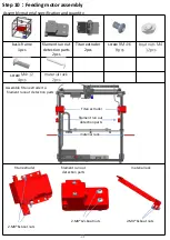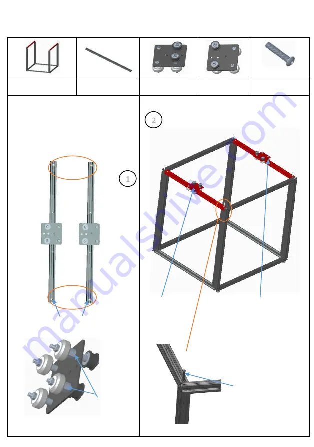
Assembly material specification and quantity
:
base frame
1pcs
aluminum 2
20*20*530 2pcs
left sliding parts
1pcs
right sliding
parts 1pcs
screws RM5*25
4pcs
2.Note the direction of the slide. The front
of the slide should be on the same side as
the counterbore of the guide, as shown in
the figure.
1
Eccentric nut
Screw RM5*25 do not lock the Y-axis aluminum
profile 2 to facilitate subsequent adjustment
left sliding parts
right sliding parts
2
4-M5*25
5
Pay attention the direction
of the counterbore
Note: slide the slider without shaking
No gap, smooth sliding
Step 2: Sliding plate assembly
1.Take out thealuminum 2 and put it
into the left and right sliding parts
respectively, as shown in the figure.
Summary of Contents for X5SA-400-2E
Page 1: ...X5SA 2E Installation Manual ...
Page 21: ...17 5 Interface operation and printing ...
Page 26: ...2 How to use slice software Type setting follow the steps below to complete the setting 22 ...
Page 31: ......
Page 32: ......


