4
EN
Introduction
Thank you for purchasing this Triton product. This manual contains
information necessary for safe and effective operation of this
product. This product has unique features and, even if you are
familiar with similar products, it is necessary to read this manual
carefully to ensure you fully understand the instructions. Ensure all
users of the product read and fully understand this manual.
Product Familiarisation
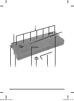
1. Jig
2. Drill Guide x7
3. Drill Bit
4. Locating Pin
5. Hex Key
6. Depth Collar
7. Clamping Area
8. Joining Hook
9. Joining Pin
Intended Use
Jig for creating locating holes for adjustable shelving units such as
cabinets, bookshelves etc.
Before Use
WARNING
: Always adhere to all safety advice and instructions
for any power tool used in conjunction with this product.
Connecting multiple Jigs
Two or more Jigs (1) can be connected using the snap-on system,
to produce a continuous Jig, covering the whole length to be drilled.
1. Line up the ends of Jigs to be joined, at 45o to each other
2. Swivel the Jigs in opposite directions to engage the Joining
Hooks (8) with the Joining Pins (9). Apply enough pressure to
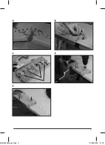
snap into place (Image A)
3. Attach additional Jigs as required
Operation
WARNING
: NEVER hold the Jig (1) by hand when drilling, it
must be clamped securely to the workpiece. Failure to do so could
result in misaligned holes, damage to the tool and/or cause serious
personal injury.
1. To set the drill depth place the Drill Bit (3) in one of the Drill
Guides (2) and align the Drill Bit with the edge of the workpiece
(Image B)
2. Place the Depth Collar (6) over the Drill Bit and set the Drill Bit
to the correct depth (Image B)
3. Tighten the grub screw on the Depth Collar using the Hex Key
(5), to lock the Depth Collar in place (Image B)
4. Use the pull-out guides on the underside of the Jig (1) (Image
C) to set the required distance from the edge of the workpiece.
Note
: There are 2 sets of guides to allow for 2 different distance
settings
5. Locate the guides against the edge of the workpiece (Image D)
and position the Jig
6. Clamp the Jig in place using the Clamping Area (7) (Image D)
7. Connect a drill (not supplied) to the Drill Bit
8. Place the Drill Bit into one of the Drill Guides until the tip
connects with the workpiece
9. Start the drill and gently drill the hole until the Depth Collar
connects with the Jig (Image D)
Note
: Use the drill on the fast setting and maintain a high speed
whilst drilling.
10. Remove the Drill Bit from the Drill Guide and switch off the drill
11. Continue to drill holes using the remaining Drill Guides
12. Remove the clamp and reposition the Jig to continue drilling
the sequence of holes
13. Position the Jig using the Locating Pin (4) through the first Drill
Guide into the last hole in the row of holes just drilled (Image E)
14. Re-clamp the jig and continue drilling the holes
Note
: If there is not enough room for the full length of the Jig at
the end of the sequence of drilled holes, then use whichever of the
holes that will position the Jig accordingly.
Note
: The Jig can be used without the guides, however, an
alternative method for aligning the Jig will need to be implemented
to ensure accurate alignment of the holes.
Accessories
A full range of accessories including Drill Bits, Locating Pins and
Depth Collars, is available from your Triton stockist.
Maintenance
Keep the Jig clean. Do not allow sawdust to build up around the Jig.
Clean regularly with a soft brush or vacuum, clean resin off with a
suitable solvent
Contact
For technical or repair service advice, please contact the helpline on
(+44) 1935 382 222
Web
: tritontools.com/en-GB/Support
Address
:
Powerbox
Boundary Way
Lufton Trading Estate
Yeovil, Somerset
BA22 8HZ, United Kingdom
Original Instructions
303468_Manual.indd 4
27/02/2019 15:31


