background image

1

5

8

3

6

10

2

9

4

7

11

12

13

4

5

49

9 – Display and Configuration 

(continued)

9-6 Maintenance 

(continued)

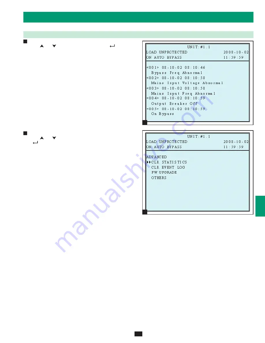
Event Log


Use “ ” or ” ” to read the event log, then press”

 ” to 

confirm.

Advance


Use “ ” or ” ” to select the “ADVANCED” item, then press  

 ” to confirm.

The “ADVANCED” item includes “clear statistics”, “clear event 
log” “firmware upgrade” and “other status monitor for service”.

(This item is only accessible for administrator! The Password will 
be required to confirm again.)

Warning: Clearing or erasing the event log may invalidate 
warranty claims. All warranty claims must be accompanied by 
supporting event log information.

Press “ESC” to return to the “UPS SETUP” menu.

4

5

Summary of Contents for SmartOnline SU80K

Page 1: ...for mobile applications 1111 W 35th Street Chicago IL 60609 USA www tripplite com support Copyright 2010 Tripp Lite All trademarks are the sole property of their respective owners Owner s Manual PRO T...

Page 2: ...e UPS 22 8 6 Shutdown Procedure Single UPS 22 8 7 Preliminary Checklist Parallel UPS 23 8 8 Start Up Procedure Parallel UPS 24 8 9 Shutdown Procedure Parallel UPS 25 8 10 Manual Bypass Procedure Paral...

Page 3: ...Internal N 1 power module redundancy Built in parallel redundancy 1 1 capability for increased capacity or fault tolerance Up to 80kVA capacity in a compact footprint up to 160kVA in parallel configur...

Page 4: ...on adjustments within the final installation area only The casters are not designed for moving the UPS system over longer distances The casters are not designed to provide long term support for the UP...

Page 5: ...e battery supply is connected Service and repair should be performed by trained personnel only while the UPS system is turned off or placed into bypass mode Disconnect internal batteries if present be...

Page 6: ...to turn the UPS system s inverter ON OFF Button Press and hold this button for 3 seconds to turn the UPS system s inverter OFF If the UPS system is in online normal mode it will switch to auto bypass...

Page 7: ...e number of internal power modules varies by model The internal power modules are capable of N 1 redundancy Main Input Circuit Breaker Switch Q1 Controls AC input power to the UPS system during online...

Page 8: ...em to another UPS system of identical type and capacity for use in a parallel redundancy 1 1 configuration See Section 6 Wiring and Section 7 Operating Modes for more information Input Dry Contact Int...

Page 9: ...m if it has been damaged or mishandled Confirm that the shipping container is upright and use a screwdriver to remove its top panel front panel and back panel Also remove the plastic wrap and interior...

Page 10: ...e with the UPS system s input requirements See Section 11 Specifications for more information about input requirements and floor loading requirements The UPS system must be installed in a clean secure...

Page 11: ...connection to an IT power distribution system that requires neutral isolation upon disconnect the disconnect device must be a four pole device and must disconnect all line conductors and the neutral...

Page 12: ...inet Breaker Switch Output External Battery Connection 12 6 Wiring continued SU80K and BP480V40C shown for illustration only consult the battery cabinet s documentation for exact specifications 6 3 UP...

Page 13: ...H 78AH 103AH 140AH 250A CB AC DC MAIN INPUT Q1 Q2 Q3 Q4 OUTPUT DC AC XFMR XFMR 13 6 Wiring continued 6 4 External Battery Cabinet Wiring Diagrams continued 6 5 Electrical and Cable Data Input and Outp...

Page 14: ...tery connection terminals of the UPS system See Section 6 3 and the external battery cabinet s documentation for terminal block diagrams See Section 6 4 for wiring diagrams See Section 6 5 for cable s...

Page 15: ...irst confirm that the main input circuit breaker switch Q1 and the bypass input circuit breaker switch Q2 are both off Second confirm that the manual bypass circuit breaker switch Q3 is off Third conf...

Page 16: ...rts 2 UPS systems 1 1 redundancy Do not attempt to link more than two UPS systems via parallel configuration The UPS systems must have the same rating and capacity for parallel configuration installat...

Page 17: ...r transforms the DC power to precision regulated pure sine wave AC power that supports the operation of connected equipment 7 3 Auto Bypass Mode Single UPS If the inverter malfunctions due to excessiv...

Page 18: ...apacity Under parallel redundancy the total load is shared by two UPS systems If one of the UPS systems malfunctions the total connected equipment load is supported by the remaining UPS system If the...

Page 19: ...3 Q4 CB5 MAIN STS Q2 XFMR XFMR UPS1 UPS2 19 7 Operating Modes continued 7 8 Manual Bypass Mode Parallel UPS Similar to manual bypass mode for a single UPS system Section 7 4 except with parallel 1 1 U...

Page 20: ...t Breaker Switch 8 2 Preliminary Checklist Single UPS All circuit breaker switches should be off including the breaker of the external battery cabinet if present Confirm that no voltage potential exis...

Page 21: ...urce is normal the UPS system is ready for start up Press the ON button A for 3 seconds until you hear a beep then release the button The inverter will activate and synchronize with the bypass source...

Page 22: ...the BATTERY BREAKER On 80K units the BATTERY BREAKER is on the back of the matching battery cabinet Note Some external battery cabinets may have the BATTERY BREAKER behind the front door or elsewhere...

Page 23: ...Load Protected On Line Mode Confirm there are no active alarms present on the display and audible beeping If an alarm is present press the UP or DOWN arrows to display the active alarm Correct the act...

Page 24: ...initialization process the LCD screen will show ON AUTO BYPASS and the BYPASS LED will illuminate Switch on the main input circuit breaker switch Q1 of each UPS system Press the ON button A of one of...

Page 25: ...MODE If the total connected equipment load is too large to be handled by a single UPS system both UPS systems will shut down their inverters and switch to bypass mode and their LCD screens will read O...

Page 26: ...UPS system both UPS systems will shut down their inverters and switch to bypass mode and their LCD screens will read ON AUTO BYPASS Repeat step 1 for the second UPS system you wish to shut down Switch...

Page 27: ...s input circuit breaker switch Q2 and the output circuit breaker switch Q4 of each UPS system Confirm that the LCD screens of both UPS systems read ON MANUAL BYPASS then switch off the manual bypass c...

Page 28: ...ss mode FAULT Red LED Illuminated when any fault occurs LCD Status Display Multi language display ESC Escape Button Escape Page Up Scroll Buttons and Scroll cursor up or down Enter Button Enter Confir...

Page 29: ...any event occurs you will see the sign flashes You can press to see the details For example Press again to go to the next message If there is no further message the screen will return to the default...

Page 30: ...tinued 9 3 1 Status Display continued The loads are supplied by bypass source due to initial startup of the UPS The UPS is starting up by battery power The UPS system is in auto bypass mode Connected...

Page 31: ...ay continued The UPS system is operating in online normal mode Connected equipment loads will receive battery backup power if the mains utility or generator power source fails The UPS is in battery ba...

Page 32: ...tem is in manual bypass mode in order to allow qualified service personnel to perform maintenance or repair on the UPS system Connected equipment loads will lose power if the bypass power source fails...

Page 33: ...uration continued 9 4 Main Menu continued UPS System Measure Menu 1 Press the enter button to select MEASURE from the main menu 2 Use the scroll buttons or to scroll through the available data screens...

Page 34: ...Qualified service personnel User The authorization is only to check the parameter but not to configure The password consists of 4 numerals Press the scroll down button or the scroll up button to sele...

Page 35: ...sword is wrong press to reselect 9 5 1 Bypass Setup Enter the UPS system setup menu Use the scroll buttons to move the cursor to BYPASS SETUP then press the enter button From the VOLTAGE RANGE screen...

Page 36: ...enter button to confirm the setting Note Press the ESC button to return to the previous menu Press ESC to return to the UPS SETUP menu 9 5 2 Output Setup Use or to select OUTPUT SETUP then press to c...

Page 37: ...e From the FREQUENCY screen use the scroll buttons to select the desired setting and press the enter button to confirm the setting Note The output frequency setting is only used when the UPS system st...

Page 38: ...or to select the desired number of modules for redundancy usually one for redundancy then press to confirm This feature allows the user to determine an acceptable power output limit to guarantee a red...

Page 39: ...ame For example BP480V26B 26 AH BAT STRINGS Enter the number of battery strings connected to the UPS system For example SU80K with two BP480V55 enter 2 CHARGER CURRENT See Section 9 5 4 for informatio...

Page 40: ...enter button to confirm the settings Battery Next Replace Date Use or to set the next replace date then press to confirm When the selected date is reached the UPS will alarm and a message will be sho...

Page 41: ...otal to a maximum of 5 amps per internal power module multiplied by the number of modules For example the SU80K has four internal power modules so its charger current range is 2 20 amps Set the charge...

Page 42: ...ess to confirm Parallel Group The parallel group setting tells the UPS that it is operating in parallel Group 1 is the default setting See Section 6 Wiring for wiring considerations Note Possible sett...

Page 43: ...confirm Use or to select the desired item then press to confirm Battery Auto Test Use or to select the desired item then press to confirm Allows for scheduling of a battery test frequency for the dura...

Page 44: ...d will be needed Force Boost Charge Press to execute FORCE BOOST CHARGE Enables activating the boost charge which is at a voltage of 20 higher than the nominal setting Warning Boosting battery charge...

Page 45: ...sword to confirm the operation Press ESC to return to the UPS SETUP menu 9 5 7 Local Setup Use or to select LOCAL SETUP then press to confirm Use or to select the desired item then press to confirm Fr...

Page 46: ...t Use or to change the date format then press to confirm This item is user accessible From the SERIAL COM ID screen use the scroll buttons to select the desired serial port ID and press the enter butt...

Page 47: ...settings Note The administrator password should be used by qualified service personnel only User Password The password consists of 4 digits From the PASSWORD CHANGE screen use the scroll buttons and t...

Page 48: ...mber of the UPS unit Use or to select the desired item then press to confirm Firmware Version Use or to select the F W version item then press to confirm The display will show the firmware version of...

Page 49: ...to confirm The ADVANCED item includes clear statistics clear event log firmware upgrade and other status monitor for service This item is only accessible for administrator The Password will be requir...

Page 50: ...ets Input Contact A Pin 1 2 rated for 12V DC minimum 0 1A nominal Input Contact B Pin 3 4 rated for 12V DC minimum 0 1A nominal See section 10 5 P3 External Battery Cabinet Temperature 1 Temperature S...

Page 51: ...5 Auxiliary Dry Contact Input Circuit Diagram The auxiliary dry contact input connections P2 allow the UPS system to receive external signals These contacts are normally open External contacts rated...

Page 52: ...llel redundancy installation the parallel communication is not normal Output overload warning shutdown The load exceeds the capacity of the UPS system Power module fault shutdown The UPS system has sh...

Page 53: ...T DRY CONTACT 53 10 Communications continued 10 9 Output Dry Contact Circuit Diagram The UPS system has six dry contact output connections These contacts can be normally open or normally closed Contac...

Page 54: ...age AC output voltage AC input frequency internal temperature set shut down delay time enable disable alarm and remote shutdown Hardware Baud Rate 2400 BPS Data Length 8 bits Stop Bit 1 bit Parity NON...

Page 55: ...erface Standard RS 232 Dry Contact Optional SNMPWEBCARD Others Parallel Redundancy Yes 1 1 for 2 UPS systems of the same type and capacity only EPO Standard Local and Remote SRAM Event Log 500 Records...

Page 56: ...R OR TO DAMAGE RESULTING FROM ACCIDENT MISUSE ABUSE OR NEGLECT SELLER MAKES NO EXPRESS WARRANTIES OTHER THAN THE WARRANTY EXPRESSLY SET FORTH HEREIN EXCEPT TO THE EXTENT PROHIBITED BY APPLICABLE LAW A...

Reviews: