


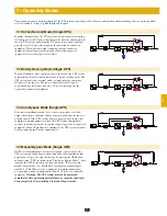


1
5
8
3
6
10
2
9
4
7
11
12
13
Main
Input
O
OFF
O
OFF
O
OFF
O
OFF
Front Panel
Back Panel
Control Panel
1
2
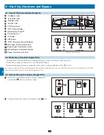
A
E
F
G
K
A
B
C
D
H
I
J
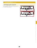
Main
Input
O
OFF
O
OFF
O
OFF
O
OFF
Q4
Q2
Q3
Q1
Front Panel
Back Panel
Main
Input
O
OFF
O
OFF
O
OFF
O
OFF
Front Panel
Back Panel
Q3
20
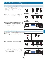
8 – Start-Up, Shutdown and Bypass
8-1 Control Panel and Breaker Diagrams
“NORMAL” LED
•
“BATTERY” LED
•
“BYPASS” LED
•
“FAULT” LED
•
LCD Status Screen
•
“ESC” (Escape) Button
•
Scroll Buttons (
•
and )
Enter Button (
•
)
ON Button
•
OFF Button
•
“EPO” (Emergency Power Off) Button
•
Main Input Circuit Breaker Switch
•
Bypass Input Circuit Breaker Switch
•
Manual Bypass Circuit Breaker Switch
•
Output Circuit Breaker Switch
•
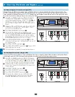
8-2 Preliminary Checklist (Single UPS)
All circuit breaker switches should be off, including the breaker of the external battery cabinet (if present).
•
Confirm that no voltage potential exists between Neutral and Ground.
•
Confirm that the input power source matches the rating (voltage, frequency and phase) of the UPS system.
•
Note: After start-up, the UPS system will perform a brief self-test and display the results on the LCD screen. After a successful self-test, the UPS
system will provide AC power to the connected equipment load.
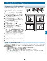
8-3 Normal Start-Up Procedure (Single UPS)
If there is an external battery cabinet connected, switch on the
•
circuit breaker
A
of the external battery cabinet.
Confirm that the manual bypass circuit breaker switch
•
Q3
is off.
A
B
C
D
E
F
G
H
I
J
K
Q1
Q2
Q3
Q4
Circuit Breaker Switches
1
2


