


1
5
8
3
6
10
2
9
4
7
11
12
13
1
2
A
A
B
B
5
A
3
4
6
Main
Input
O
OFF
O
OFF
O
OFF
ON
I
Front Panel
Back Panel
Q2
Main
Input
O
OFF
O
OFF
ON
I
ON
I
Front Panel
Back Panel
Q1
Main
Input
O
OFF
ON
I
ON
I
ON
I
Front Panel
Back Panel
Q4
24
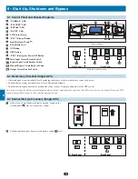
8-8 Start-Up Procedure (Parallel UPS)
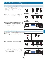
Connect the parallel
•
configuration
cable
A
to the DB9 parallel
redundancy port
B
of each UPS system.
Note: Before starting up
parallel UPS systems, ensure the "Parallel ID" is different for each
UPS and that the parallel group is set. (See section 9-5-5.)
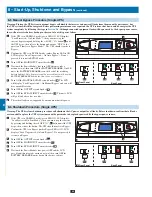
If the UPS systems have external battery cabinets connected,
•
switch on the external battery cabinet circuit breaker switch
A
of
each battery pack.
1
2
8 – Start-Up, Shutdown and Bypass
(continued)
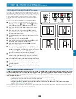
Switch on the bypass input circuit breaker switch
•
Q2
of each
UPS system. After a brief initialization process, the LCD screen
will show “ON AUTO BYPASS” and the “BYPASS” LED will
illuminate.
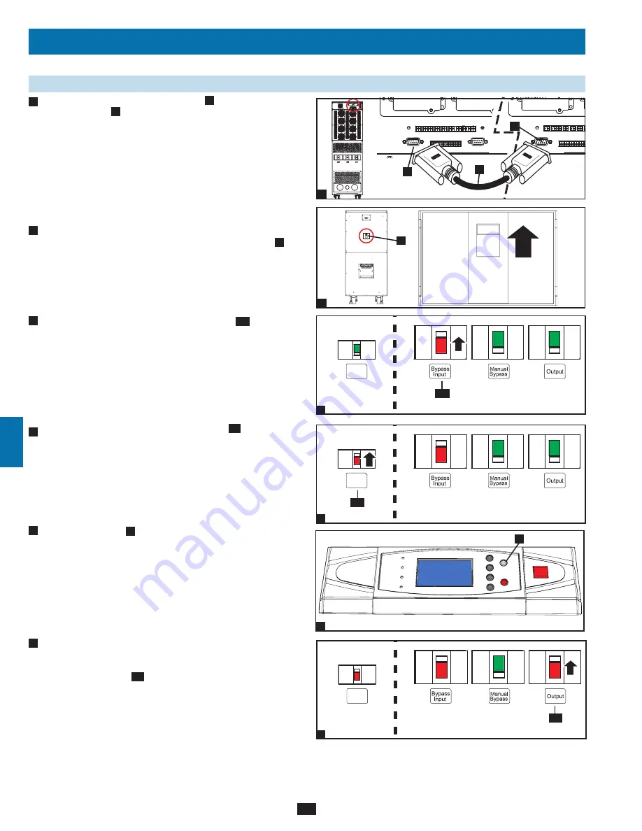
Switch on the main input circuit breaker switch
•
Q1
of each UPS
system.
Press the ON button
•
A
of one of the UPS systems for 3 seconds
(until you hear a beep), then release the button. The inverter will
activate and synchronize with the bypass source. Press the ON
button for the other UPS system for 3 seconds (until you hear a
beep), then release the button. When the inverter of each UPS
system is operating normally, they will automatically switch from
auto bypass mode to online (normal) mode at the same time.
The “BYPASS” LED will darken and the “NORMAL” LED will
illuminate.
Check the output voltage of each UPS system. The phase deviation
•
between each UPS system should be less than 5V. If the phase
deviation is within the acceptable range, switch on the output
circuit breaker switch
Q4
of each UPS system.
Note: For more
information on checking the output voltage of each UPS system,
see
Section 9-4
.
3
4
5
6


