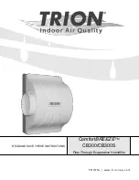
C o m f o r t
B R E E Z E
T M
M o d e l C B 3 0 0
I n s t a l l a t i o n , O p e r a t i o n , & M a i n t e n a n c e M a n u a l
8
w w w. t r i o n i a q . c o m
6. Maintenance & Troubleshooting
!
DANGER - RISK OF ELECTRIC SHOCK
Before cleaning, servicing, or parts replacement, the unit must
be disconnected from all sources of electricity.
6.1 Pad Replacement
It will become necessary to replace the pad inside your
ComfortBREEZE CB300/CB300S humidifier as time goes on.
A red LED Service indicator light may light up. This will tell
you that it is time to service your humidifier. Please refer the
following procedure.
1. Adjust Humidistat to the lowest setting to ensure that
there is no call for humidity.
2.
Ensure that power to the humidifier has been turned off
so that the humidifier will not operate while service is
being performed.
3.
Close the water supply valve so that no water may flow to
the humidifier during servicing.
4.
To remove the humidifier cover, press the release pads
as shown in Figure 10 and pull the cover toward you.
5.
To remove the evaporator pad, push the retaining clips
and pull the top pad retainer out from the base. The
retainer and pad will come out together. The drain pan
stays inside the unit. See Figure 11.
6.
Reassemble the humidifier.
7.
If required, reset the service timer (RED LED) by pressing
the reset button on the circuit board (if equipped) for 3
seconds. CB300S units with H
2
OSmart™ Technology
include a circuit board.
Figure 10
Heat Pump System: Humidifier operates
upon call-for-humidity only during a call-for-
heat.
•
DIP Switch #3: Off
•
DIP Switch #4: Off
•
Air Proving Switch: Required
•
Go Terminal: No Connection
•
W/G Terminal: No Connection
Heat Pump System: Humidifier operates
upon a call-for-humidity and will start the
HVAC blower.
•
DIP Switch #3: Off
•
DIP Switch #4: On
•
Air Proving Switch: Recommended but not required.
If no air proving switch is used, install a jumper across
the AP1/AP2 terminals
•
Go Terminal: Connected to System “G”
•
W/G Terminal: No Connection
5. Operation
Once the CB300/CB300S is installed and ready to be started,
the humidistat and DIP switches on the control board within
the humidifier unit must be configured. The CB300 without
the H
2
OSmart™ controls does not have any DIP switches to
configure. You may skip to the Preliminary Checkout and Start-
up Sequence.
5.1 Preliminary Checkout and Start-up Sequence
1. Check that unit drain plumbing is properly connected and
drained.
2. Ensure that the supply plumbing is installed properly.
3. Open cold water supply and insure water is reaching the
unit. Incoming water line should be filtered.
4.
With the unit powered, when the humidistat has a “call for
humidity”, the indicator LED will illuminate Green and the
unit will begin operation.
5. If at any point the indicator LED illuminates red or blinks
red/green alternating, a fault has been detected; service
will be required and the fault must be reset. Refer to the
Maintenance & Troubleshooting section.
6. Refer to the humidistat manual for “call for humidity”
percentage settings.
5.2 Starting/Stopping the unit
In order to start and stop the unit you must only lower the
humidistat setting to a point at which the contacts are open.
X
X
X
X
X
X
X
X
X
X


