


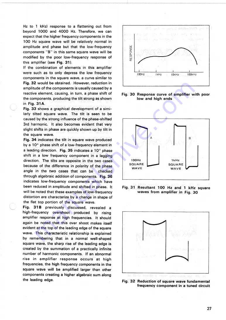
Hz to 1 kHz) response to a flattening out from
beyond 1 0 0 0 and 4 0 0 0 Hz. Therefore, w e can
expect that the higher frequency components in the
1 0 0 Hz square w a v e will be relatively normal in
amplitude and phase but that the low-frequency
components " B " in this same square wave will be
modified by the poor low-frequency response of
this amplifier (see
Fig. 31).
If the combination of elements in this amplifier
were such as to only depress the low frequency
components in the square wave, a curve similar to
Fig.
3 2
would be obtained. However, reduction in
amplitude of the components is usually caused by a
reactive element, causing, in turn, a phase shift of
the components, producing the tilt strong as shown
in
Fig. 31
A .
Fig. 3 3 shows a graphical development of a simi-
larly tilted square wave. The tilt is seen to be
caused by the strong influence of the phase-shifted
3rd harmonic. It also becomes evident that very
slight shifts in phase are quickly shown up by tilt in
the square wave.
Fig.
3 4
indicates the tilt in square wave produced
by a 10° phase shift of a low-frequency element in
a leading direction. F i g . 3 5 indicates a 1 0 ° phase
shift in a low frequency component in a lagging
direction. The tilts are opposite in the two cases
because of the difference in polarity of the phase
angle in the t w o cases that can be checked
through algebraic addition of components.
F i g . 3 6
indicates low-frequency components which have
been reduced in amplitude and shifted in phase. It
will be noted that these examples of low-frequency
distortion are characterize by a change in shape of
the flat top portion of the square wave.
F i g .
3 1 B
previously d i s c u s s e d , revealed a
high-frequency overshoot produced by rising
amplifier response at high frequencies. It should
again be noted that this over shoot makes itself
evident at the top of the leading edge of the square
wave. This characteristic relationship is explained
by remembering that in a normal well-shaped
square wave, the sharp rise of the leading edge is
created by the summation of a practically infinite
number of harmonic components. If an abnormal
rise in a m p l i f i e r r e s p o n s e o c c u r s at high
frequencies, the high frequency components in the
square wave will be amplified larger than other
components creating a higher algebraic sum along
the leading edge.
Fig. 3 0 Response curve of amplifier with poor
low and high ends
Fig. 31 Resultant 100 Hz and 1 kHz square
waves from amplifier in Fig. 30
Fig. 3 2 Reduction of square wave fundamental
frequency component in a tuned circuit
27
RESPONS
E
1 0 0 H Z
S Q U A R E
W A V E
1 k H z
S Q U A R E
W A V E


