Page 2-5
the scale base in the location provided (bag well).
5. Center the frame in the opening. Adjust the leveling legs so that the scale base is in a
level position. Make sure there is equal pressure on all four leveling feet.
6. Use the Scale Anchor Holes at each corner (
see fig. 2-2
) to secure the scale base in
place with the wood screws provided.
7.
The scale base must be grounded
with the lead attached to the top frame. The center
screw on an electrical outlet or a metal conduit is usually suitable. Leave some slack in
the wire. Do not pull the wire tight because it can negatively affect weighing
performance.
2.5
Digital Display and Keypad Installation
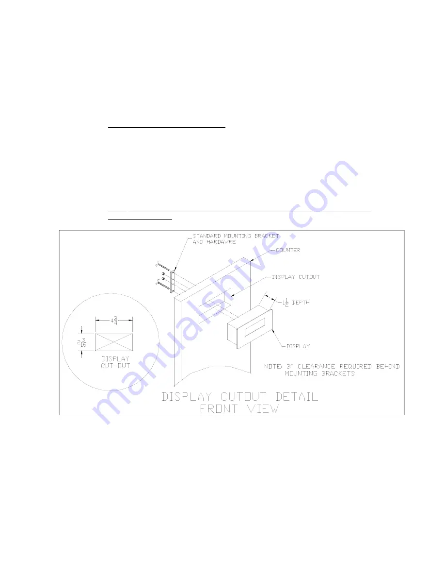
1. Refer to
Fig. 2-7
below to cut the holes and mount the dual digital display modules into
the counter.
Note
: Counter cut-outs to be located and cut by the customer or contractor unless
otherwise specified.
Fig. 2-7: Display Cut Out Detail


