


©1997-2015 TRIKDIS
13
www.trikdis.com
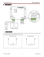
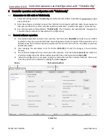
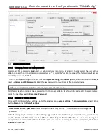
Controller GV15 Controller operation and configuration with “TrikdisConfig”
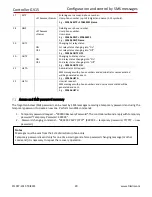
Input parameters
The controller has two inputs, upon their activation messages will be generated and reported to the administrator
level users (if set so).
6.4.1
Input type selection
To select input connection type, go to the program menu System settings, field Input options, and choose one of
two available connection type (NO, NC) next to Type of inputs IN1, IN2.
6.4.2
Message sending after inputs actuation/restoration
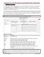
Message sending is enabled for each administrator separately. This can be done in the program menu Administrator
List, section Administrators, by marking the checkbox of required input in the columns IN1 and IN2 in the row of the
preferred administrator. SMS message text may be changed, for more details see 6.7.1 “Message text parameters“.
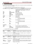
Relay parameters
The controller has two relays which can be subject to dial control or SMS message control. Relay enabling/disabling
can be reported to the users by SMS message, see 6.7 “Administrator parameters“.
6.5.1
Operation modes
Each relay can be set to operate in one of selected modes:
a)
Level
–
relay contacts status is switched to the opposite, once controller receives a control command.
b)
Pulse
–
relay contacts status is switched to the opposite to the set pulse duration, once controller receives
control command. Pulse duration 1-60 seconds.
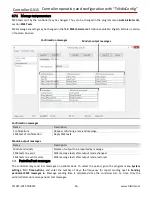
Relay operation modes are selected in the program menu System settings: for the first relay
–
in Output 1 NC and
NO options field, for the second relay
–
in Output 2 NC and NO options field. Mode type (Level, pulse) shall be
checked next to Output Mode. If pulse mode is checked, the pulse duration must be indicated at Output pulse
duration.
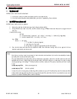
6.5.2
Control types
Relay may be controlled by:
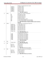
1)
SMS messages
–
both relays may be controlled by sending SMS command of respective content. This can
only be performed by the users of administrator level. For more details, see 7 “Configuration and control by
SMS messages“.
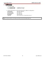
2)
Call
–
having selected the preferred mode, the first relay or both relays may be controlled, for dial control
selection see 6.5.2.1 Dial control modes. The users can control the first relay by dial control, and the
administrators - optionally the first, second or both. For Administrator control selections, see 6.7
“Administrator parameters“. Having the dial control, the controller can reject a call without answering or
reject after the set time. This can be done in the program menu System settings, field Time options, by
indicating the time in seconds (if
"
0
"
is indicated, call will be rejected without pick up) next to Hang-up after.
3)
Call (DTMF tones)
–
both relays may be controlled by calling to the inserted SIM card number or dialling the
code of respective content. This can only be performed by the users of administrator level. For more details,
see 9.2 “By DTMF tone phone call“.


