the clamping plates. For best system performance, the power (+ and -) wires
and the communication circuit wires should be twisted pair or shielded cable
installed in a separate grounded conduit to protect the communication loop
from electrical interference.
Make wire connections by stripping about
3
/
8
" (10 mm) of insulation from the
end of the wire. Then, slide the bare end of the wire under the appropriate
clamping plate (See Figure 1), and tighten the clamping plate screw. Do NOT
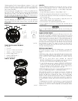
loop the wire under the clamping plate. (See Figure 2.) The wiring diagram for
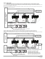
a typical 2-wire intelligent system is shown in Figure 4.
CAUTION
For system monitoring - for terminals 2, 3, 4, and 5, do not use looped wire
under terminals. Break wire run as shown in Figure 2 to provide monitoring
of connections.
FIGURE 1.
FIGURE 2.
1
1
22
33
44
55
66
C0471-07
C0473-00
TR-B200S-WH/TR-B200S-IV TERMINALS
No. Function
1. Not Used
2. Positive (+) Comm. Line In and Out
3. Negative (-) Comm. Line In and Out
4. External Supply Positive (+)
5. External Supply Negative (-)
6. Remote Annunciator
FIGURE 3. MOUNTING
C0891-07
MOUNTING
Mount the TR-B200S-WH/TR-B200S-IV mounting plate directly to an electri-
cal box. The plate will mount directly to 4" (10.2cm) square (with and with-
out plaster ring), 4" (10.2cm) octagon, 3
1
/
2
" (8.9 cm) octagon, single gang or
double gang junction boxes.
1. Connect field wiring to terminals, as shown in Figure 1 and 2.
2. Attach the mounting plate to the junction box as shown in Figure 3.
3. To mount the sounder base, hook the tab on the sounder base to the groove
on the mounting plate.
4. Then, swing the sounder base into position to engage the pins on the
product with the terminals on the mounting plate.
5. Secure the sounder base by tightening the mounting screws.
6. Install a compatible smoke sensor as described in the installation manual
for the sensor.
CAUTION
Do not over tighten mounting plate screws; this may cause mounting plate
to flex.
TAMPER RESISTANT FEATURE
NOTE: Do not use the tamper-resist feature if the removal tool is to be used.
This detector base includes a tamper-resist feature that prevents its removal
from the base without the use of a tool. To activate this feature, break the tab
from the detector base as shown in Figure 7A. Then, install the detector. To
remove the detector from the base once the tamper-resist feature has been
activated, insert a small-bladed screwdriver into the slot from the top and
press down on the lever (see Figure 7B). This allows the detector to be rotated
counterclockwise for removal. The tamper-resist feature can be defeated by
breaking and removing the plastic lever from the base. However, this prevents
the feature from being used again.
TESTING AND MAINTENANCE
Sensors and bases must be tested after installation and as an integral part
of a periodic maintenance program. Test the TR-B200S-WH/TR-B200S-IV as
follows:
NOTE: Before testing, notify the proper authorities that the smoke sensor
system is undergoing maintenance and, therefore, will be temporarily out of
service. Disable the system undergoing maintenance to prevent unwanted
alarms.
1.
Via the fire alarm control panel, command the individual
TR-B200S-WH/TR-B200S-IV to activate using the associated sensor address.
That sounder base should sound in approximately five seconds.
2. Via the fire alarm control panel, command all TR-B200S-WH/TR-B200S-IV
sounder bases to activate using group communication to all associated ad-
dresses. All devices on the loop should sound, and if a temporal tone is
commanded, the tones can be synchronized to each other.
NOTE: Synchronization requires a power supply capable of producing the Sys-
tem Sensor synchronization pulses or a synchronization module.
When performing maintenance on connected smoke sensors, carefully note
the location and address of each removed sensor. When re-installed, the
TR-B200S-WH/TR-B200S-IV will confirm that address of the sensor matches
the address stored in the sounder base memory. If there is a mismatch, this
will be communicated to the fire alarm control panel and the sounder base
can be commanded to chirp at regular intervals until the correct head is in-
stalled.
If a replacement head is installed or address changes are required, the mismatch
may be resolved at the panel by commanding the TR-B200S-WH/TR-B200S-IV
sounder base to re-enter its address learning mode and adopting the address
of the new sensor.
2
I56-3387TRG-009
4/22/2021


